In the previous blog DFT Basics Article : #12, we explored the Decompressor component of the EDT logic. In this post, we will focus on the Compressor (or Compactor) and Controller components of the EDT architecture.
Let’s get started!
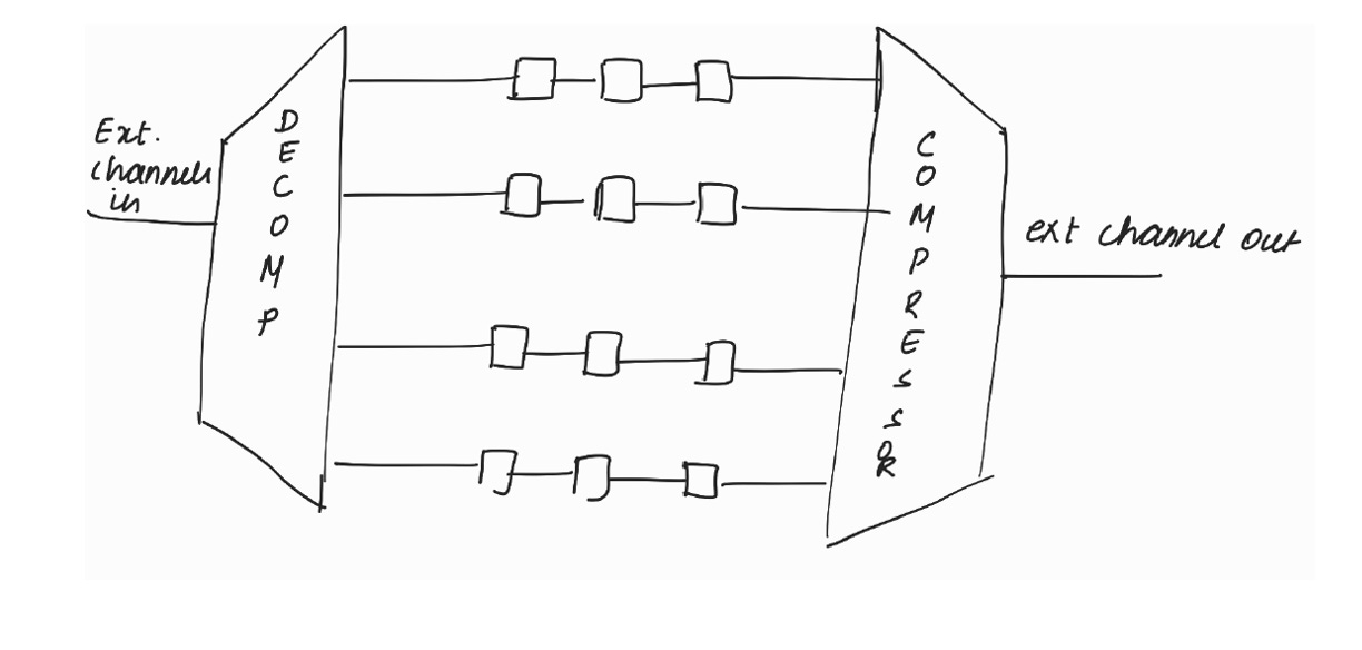
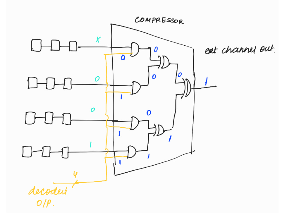
Compressor (or Compactor) :
Compressor compresses the values of all scan chains to a single value.
Compressor has levels of XORs.
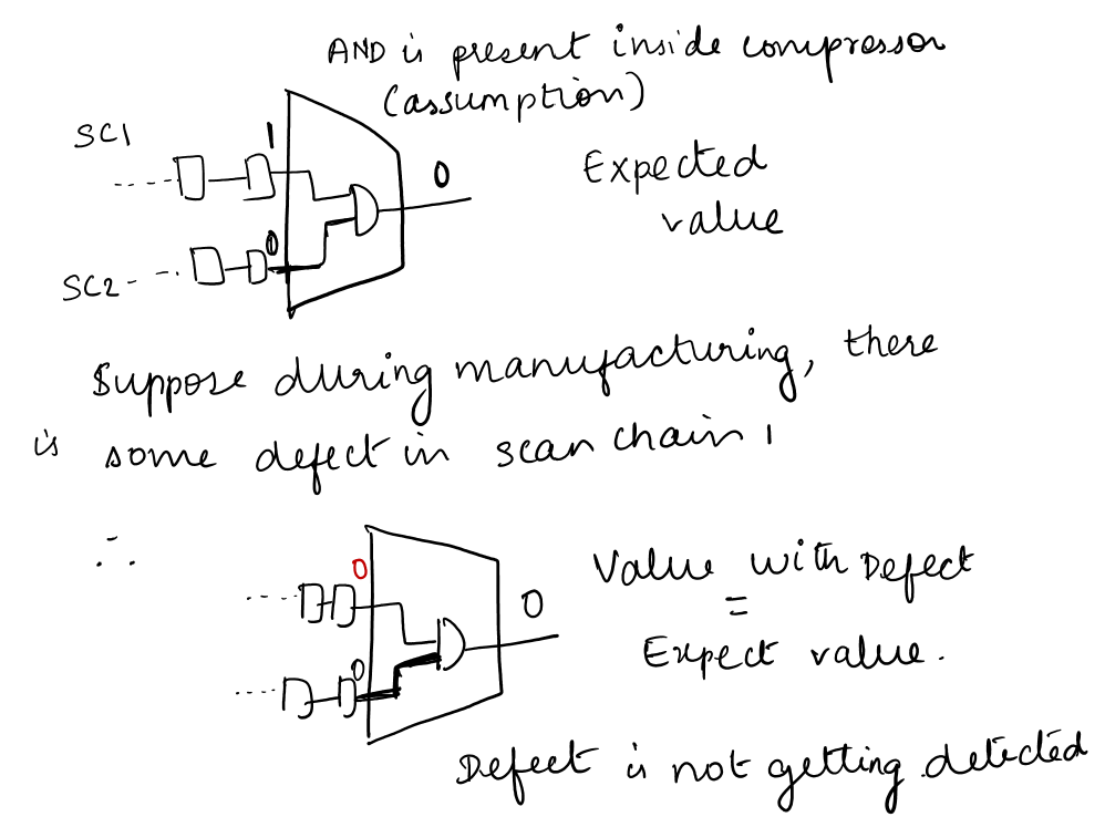
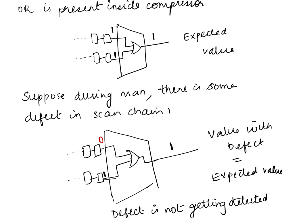
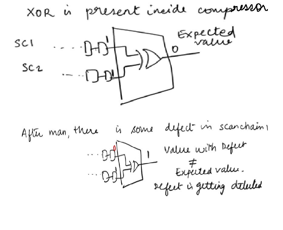
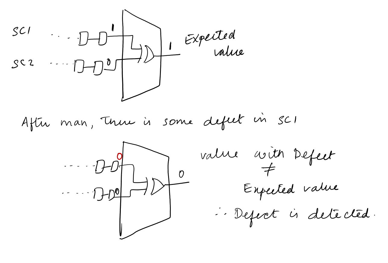
Why do we have only XOR gates inside the Compressor?
Unlike “AND” and “OR”, that ignores the other input, XOR takes care of both the paths to compact to a single path.
So XOR gates are used in the compressor.
Let's explore this concept further with the help of an illustration.
Suppose, AND gate is present inside the Compressor:
Suppose, OR gate is present inside the Compressor:
XOR gate present inside Compressor:
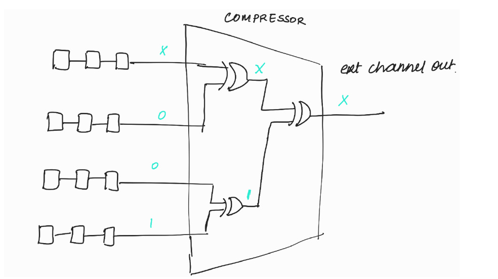
Problem in compressor logic :
X propagation.
As seen in the figure above, the propagation of an unknown value (X) on one scan chain prevents the observation of values on the other scan chains.
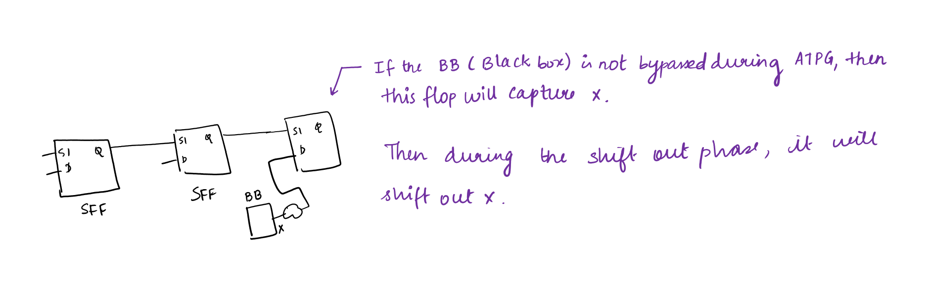
Why do scan chains propagate X?
Ifthere are any Black Boxes in the design, it’s output will be X. Black Boxes have to be bypassed during ATPG to stop the propagation of X. We have explored about Black Boxes in DFT Basics Article: #6 If Black Boxes are not bypassed during ATPG, then X will be propagated to the downstream logic and the flop will capture X (as depicted in the picture)
The captured value of the flop will be shifted out during the shift out phase. So scan chains will propagate X.
How to stop the propagation of X?
To stop the propagation of X, the masking logic is used.
Masking logic will mask the scan chains that is propagating X.
While doing fault simulation, the tool will come to know which all logics will capture X. So the tool will write a pattern in such a way that the scan chain which is propagating x will be masked.
Note : Fault Simulation is a process used by ATPG tool to generate test patterns. We will explore about fault simulation in detail during ATPG topic.
The pattern will be written in such a way that one portion of pattern will consist of masking information and the other portion of pattern will be to detect the faults.
The patterns will be shifted into the scan chain.
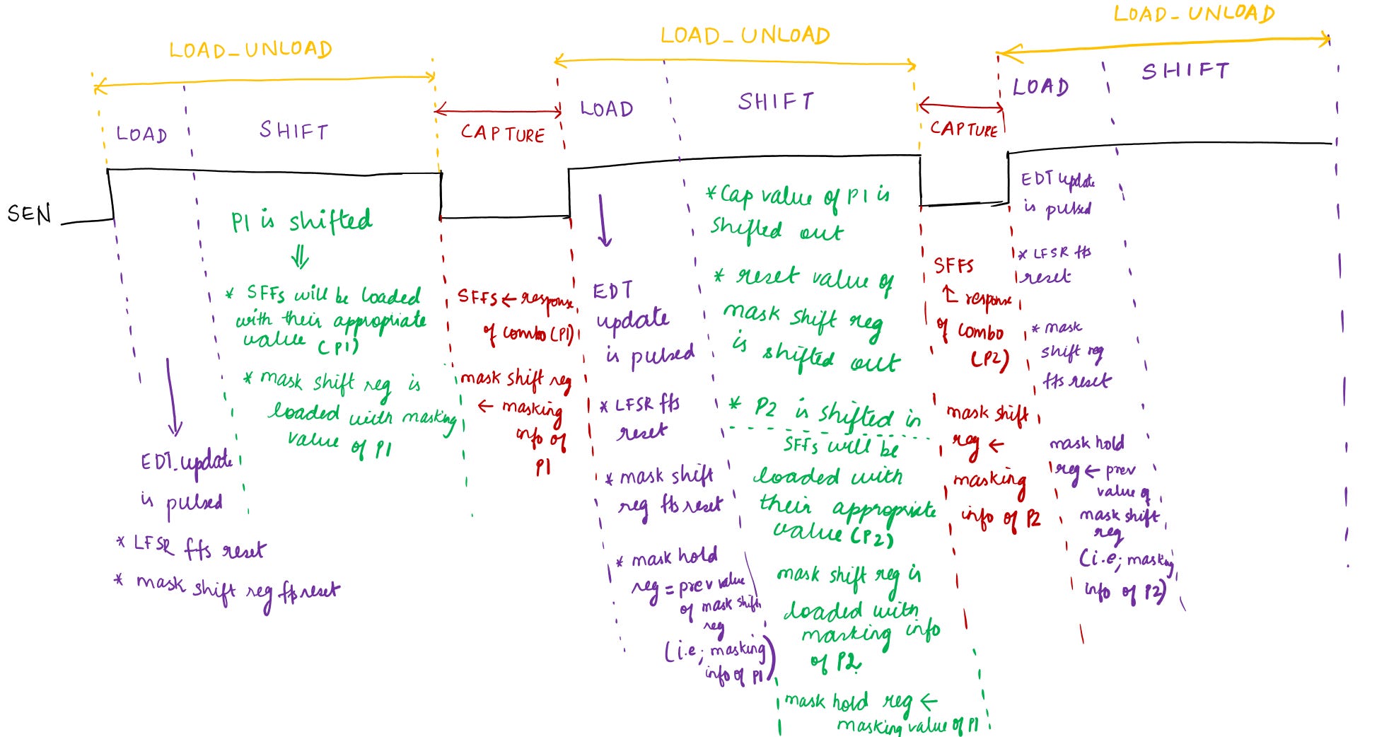
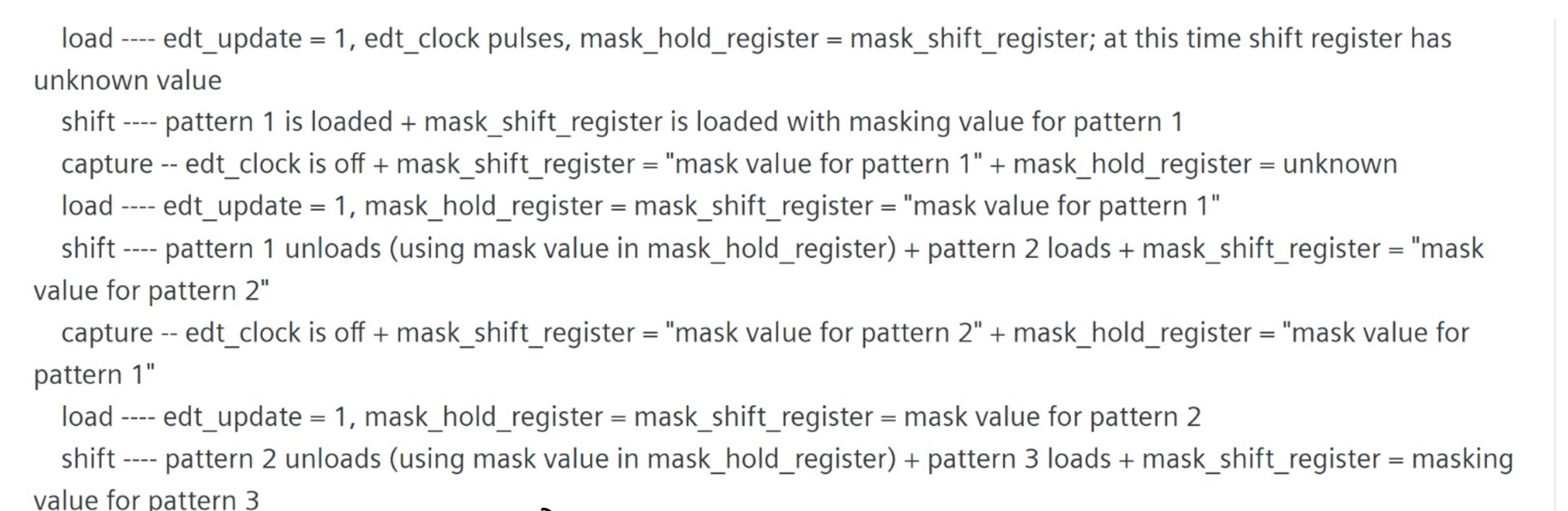
Once pattern is shifted, there will be capture phase. After capture phase, in the load phase, EDT update is pulsed. When EDT update is pulsed, the LFSR flops reset, mask shift register flops reset, the previous value which was loaded into the mask shift register will be loaded into the mask hold register.
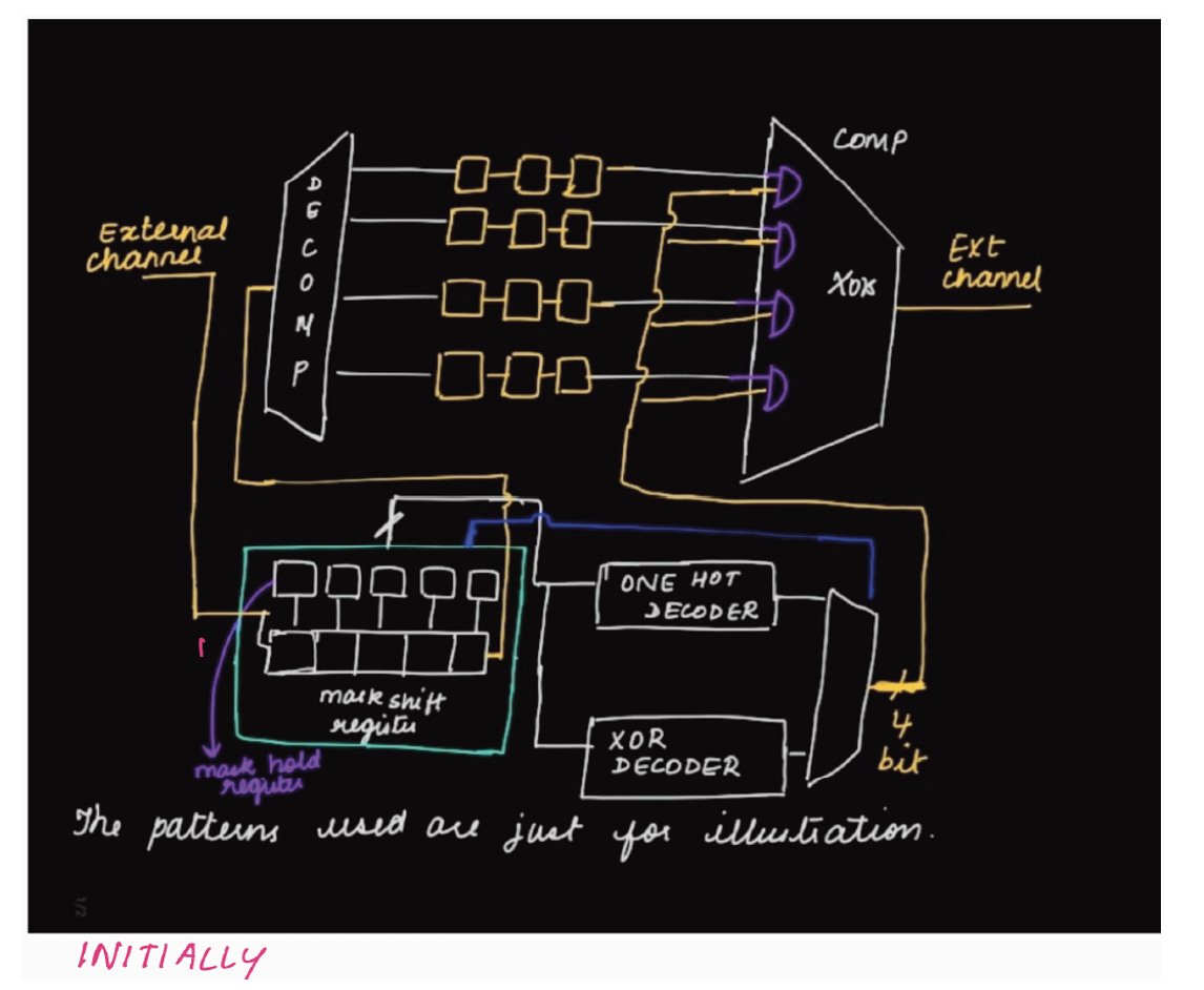
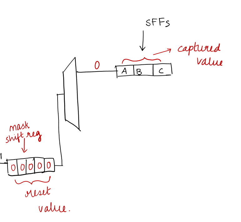
ILLUSTRATION A :
Let's explore this concept further with the help of an illustration.
Note :
This is a demonstration of how patterns will be loaded into the scan chains.
The no. of bits of mask shift and hold registers will vary from design to design based on the complexity and scan configuration.
The patterns, no .of bits of mask shift and hold register flops are assumptions (taken for illustration).
INITIALLY :
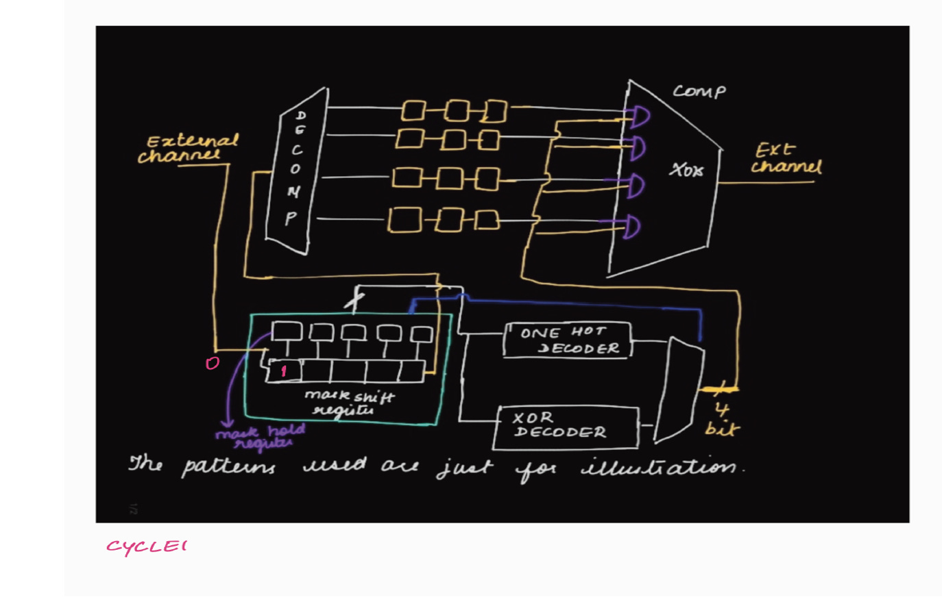
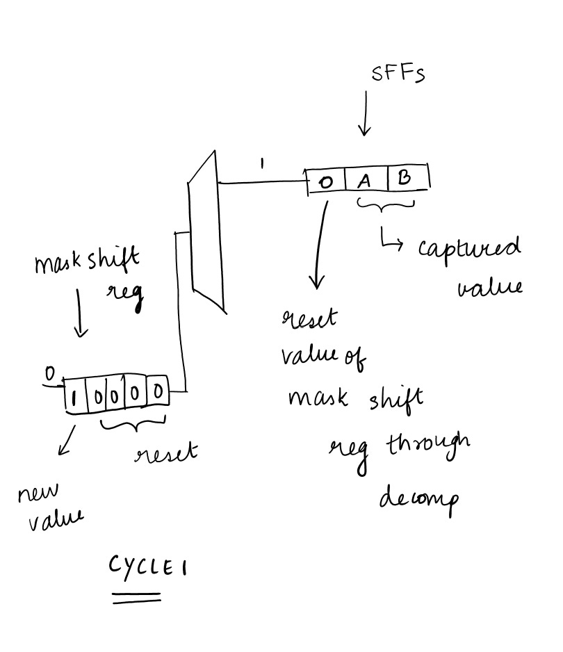
CYCLE 1 :
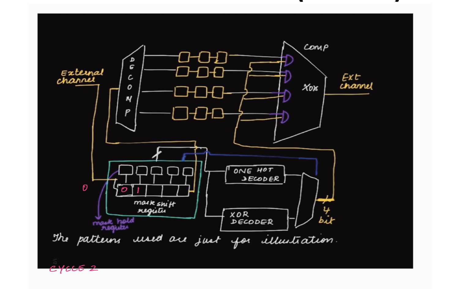
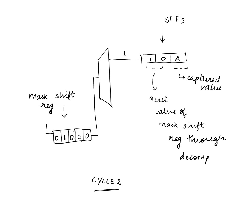
CYCLE 2:
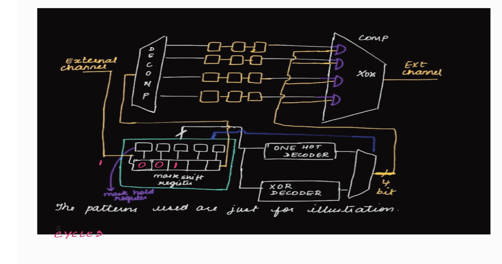
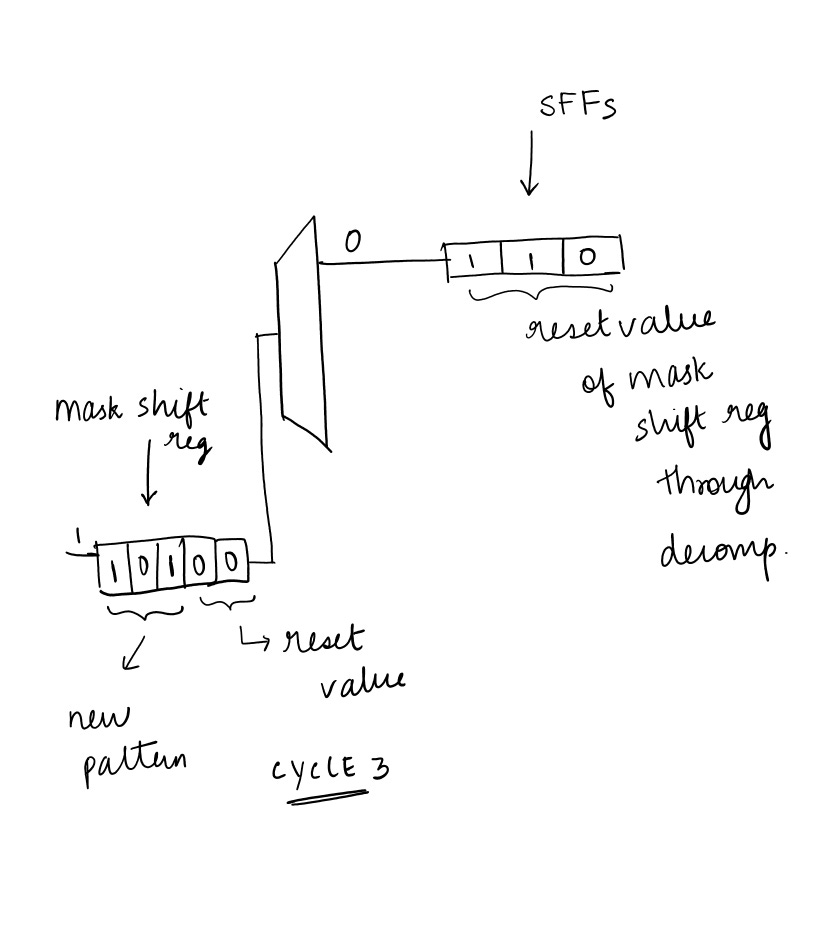
CYCLE 3:
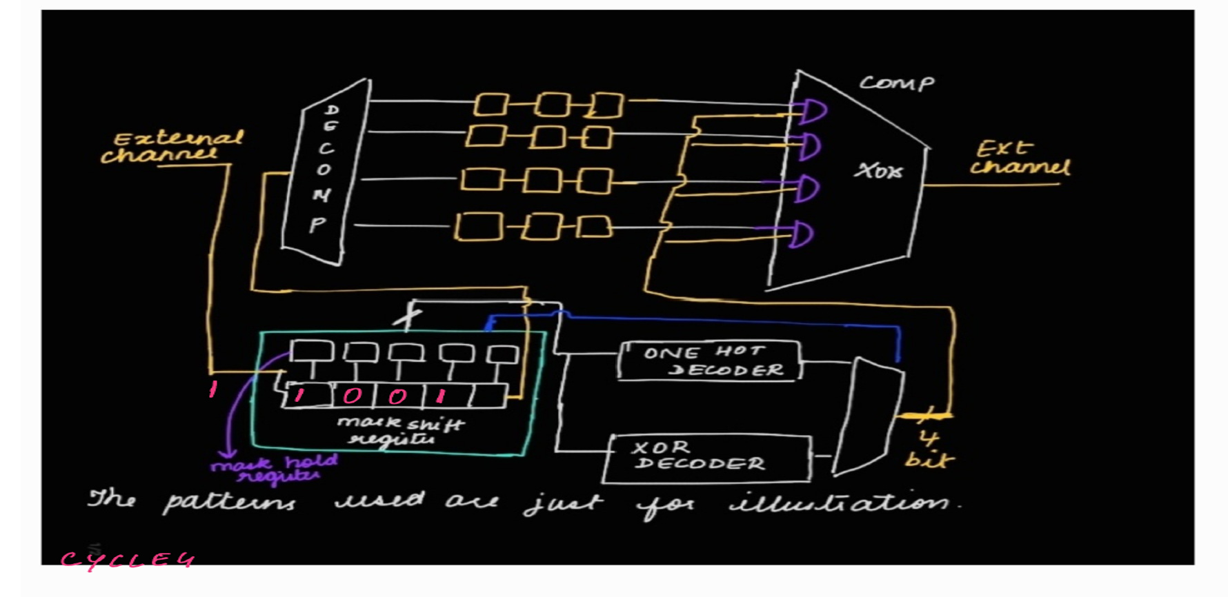
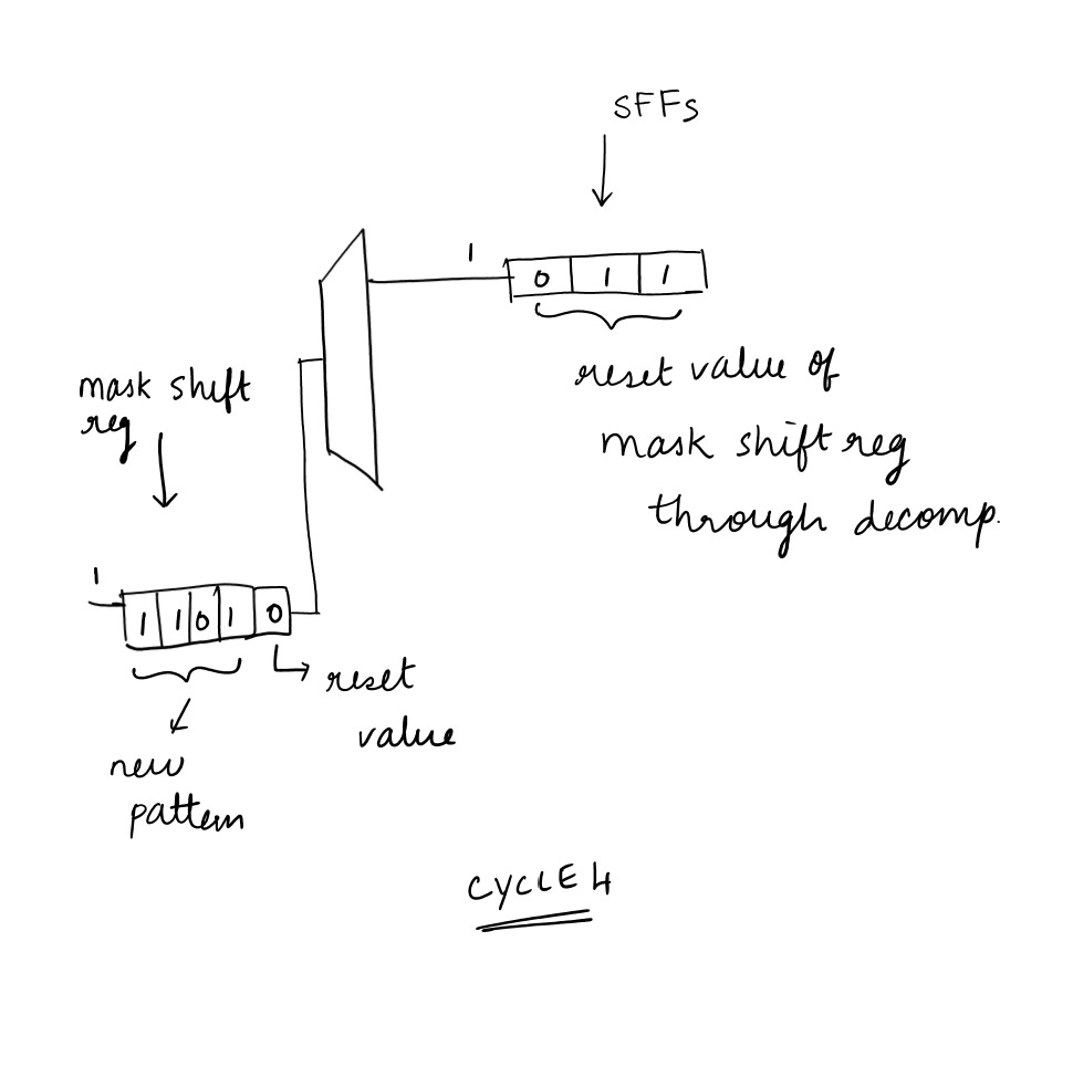
CYCLE 4:
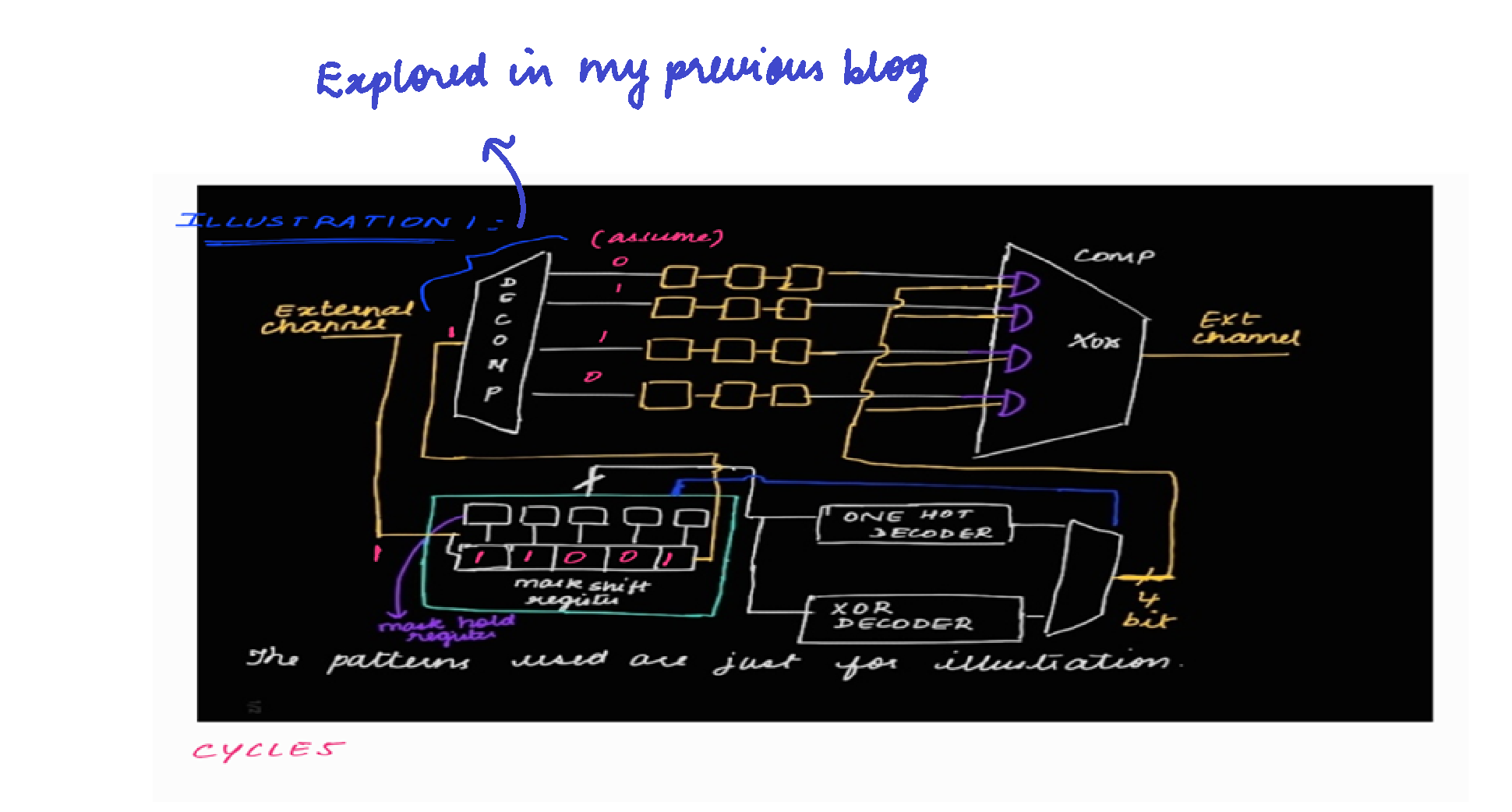
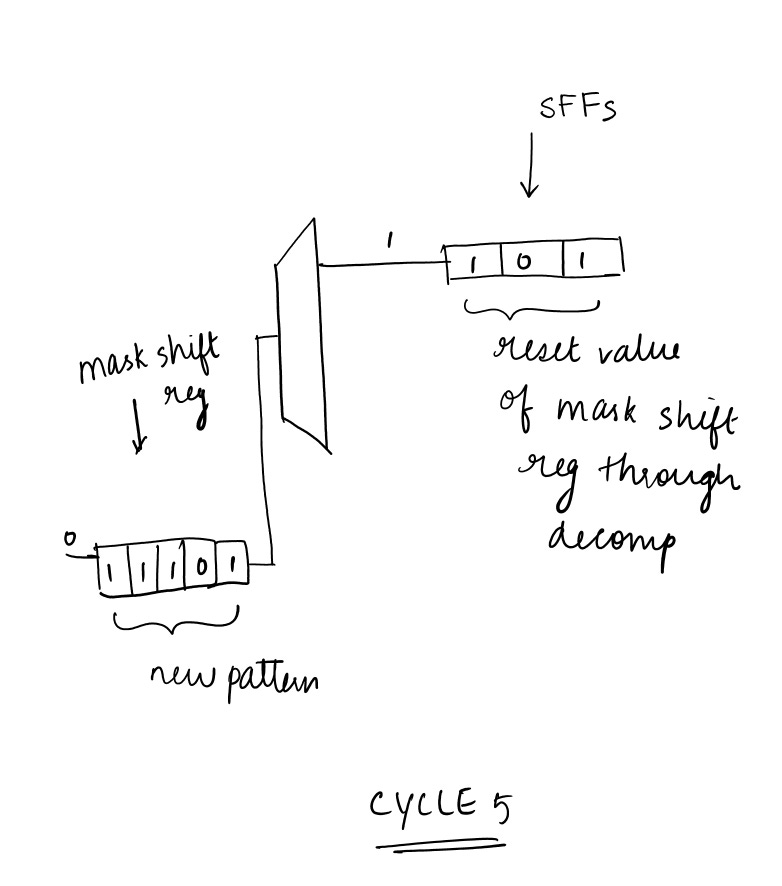
CYCLE 5:
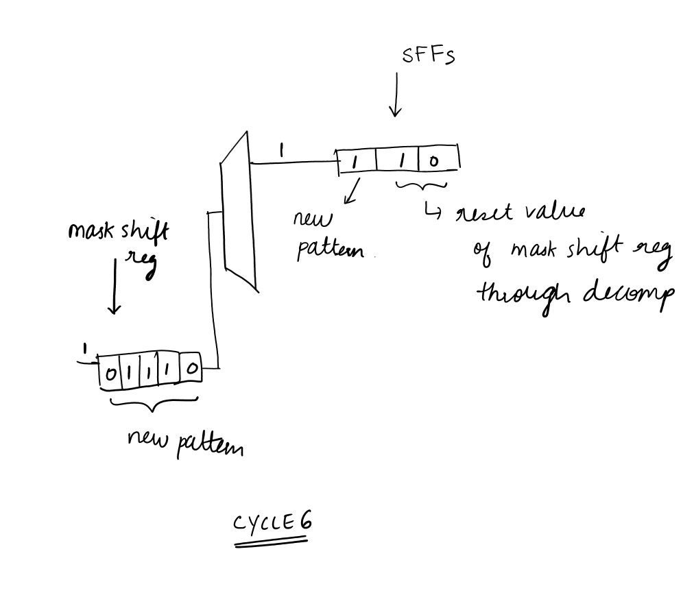
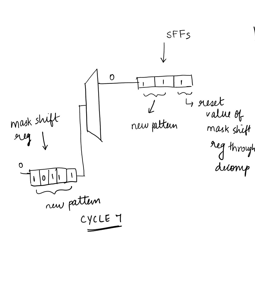
Note : The illustration of how values will be loaded into the scan chain through decompressor is depicted in my previous illustration in DFT Basics Article : #12
The values which is there at the output of the decompressor are assumed for this illustration.
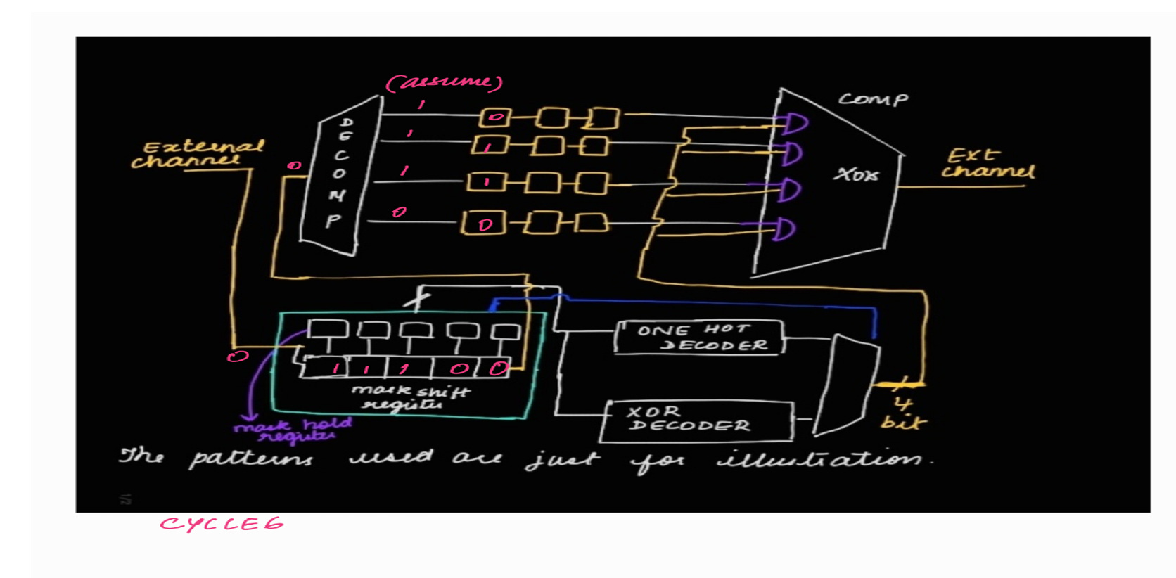
CYCLE 6:
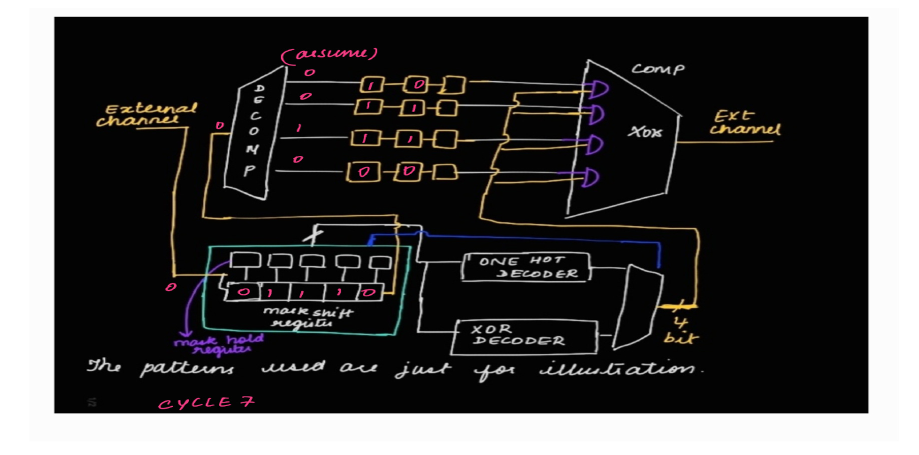
CYCLE 7:
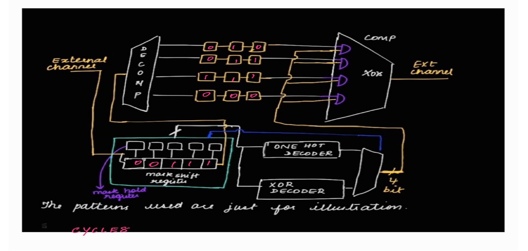
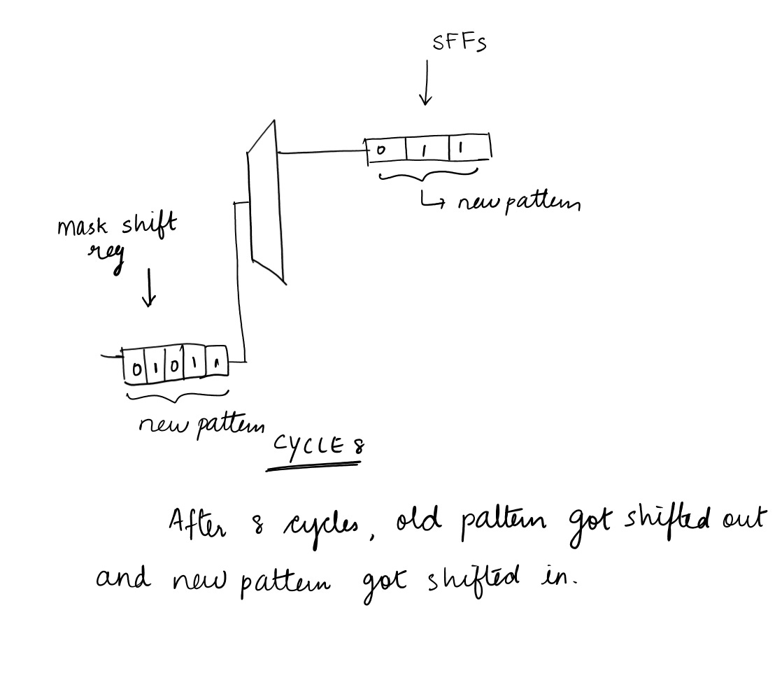
CYCLE 8:
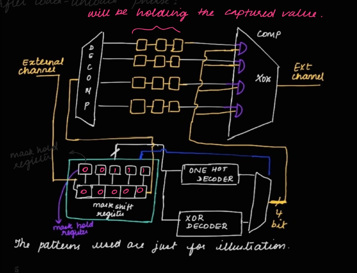
After 8 cycles, pattern 1 is loaded.
After this we will have the capture phase.
After capture phase, in the load phase, EDT update signal is pulsed. When EDT update is pulsed, LFSR flops and mask shift register flops reset and the previous value in the mask shift register will be loaded into the mask hold register.
The output of the mask hold register will be used for masking.
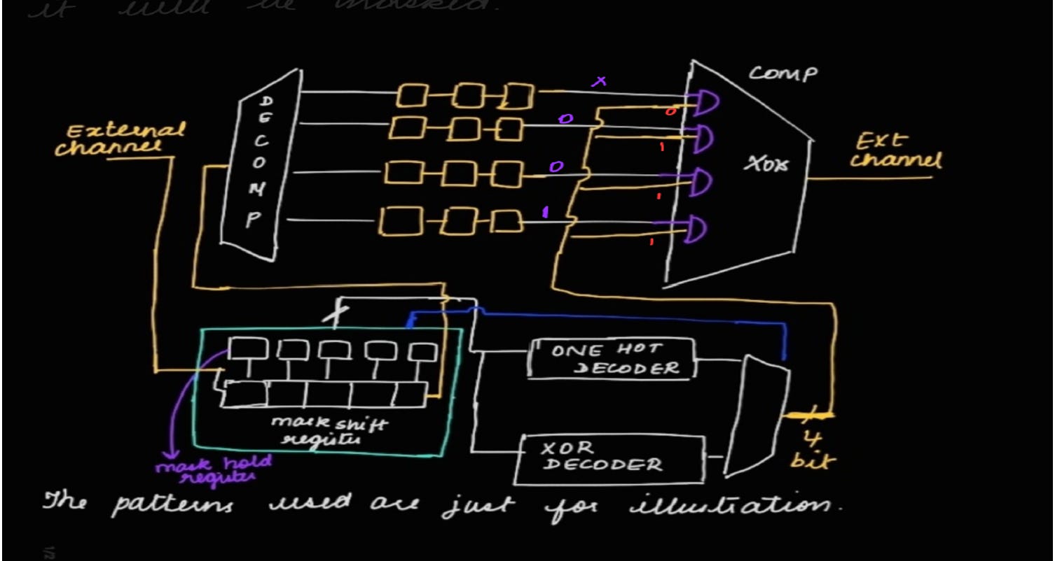
After this we have the shift phase (where old pattern will be shifted out and new pattern will be shifted in). Whichever chain is shifting out x, it will be masked.
ILLUSTRATION B:
This illustration is to demonstrate how old pattern will be shifted out and new pattern will be shifted in.
Everything is not drawn in this illustration (i.e., all the internal chains, mask hold register, decoders, compressor is not shown in the below illustration)
INITIALLY:
CYCLE 1:
CYCLE 2:
CYCLE 3:
CYCLE 4:
CYCLE 5:
CYCLE 6:
CYCLE 7:
CYCLE 8:
SUMMARY OF ILLUSTRATION A & ILLUSTRATION B :
Screenshot taken from Tessent User Manual
NOTE :
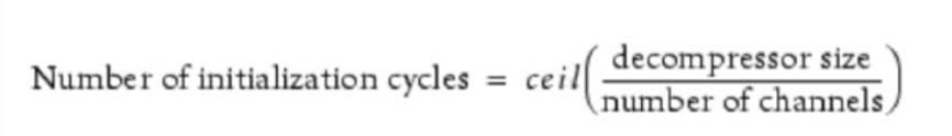
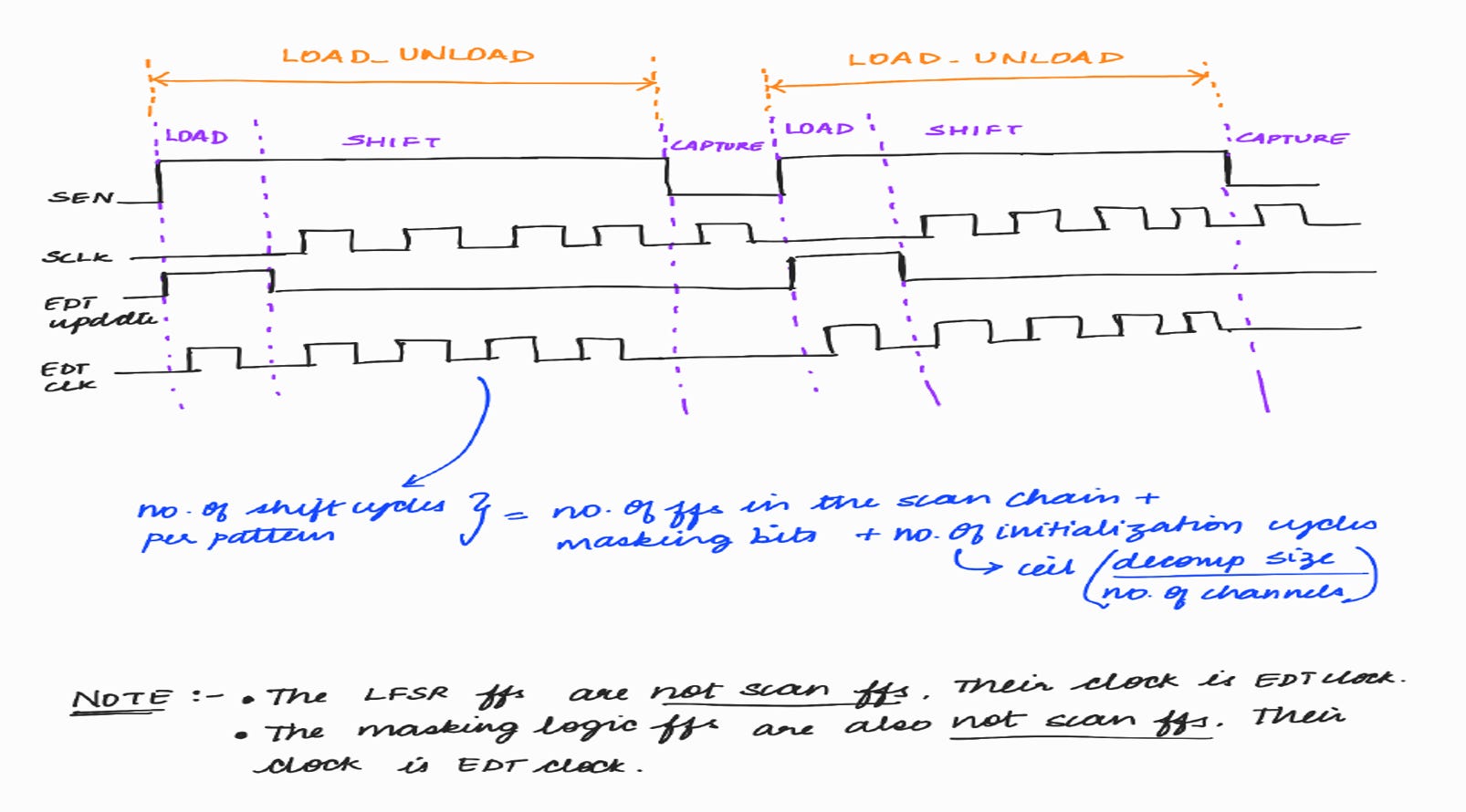
No. of shift cycles per pattern = no. of flops in the scan chain + masking bits
Tessent tool will add few more initialization cycles. Initialization cycles will be used by the TestKompress tool if it is required to detect some faults. Like in order to generate patterns to detect some faults, the initial value in LFSR is required to be at some value rather than reset value. The tool will use the initialization cycles to bring it to the required value. Else if it is not required, then the tool will maintain the reset value itself during the initialization cycles.
No. of shift cycles per pattern = 10 + 5 + ceil (8/1) = 10 + 5 + 8 = 23 shift cycles per pattern
Why do we need a mask hold register? Why can’t the output of the mask shift register directly be used for masking?
The scan chains will be propagating X during the shift out phase. So masking is required during the shift out phase. But mask shift register will reset when EDT update is pulsed and new pattern will also be shifted into the mask shift register. This will corrupt the masking information of the previous pattern.
So masking value of the previous pattern is stored into the mask hold register and the output of the mask hold register will be used for masking.
EDT Waveform:
NEED OF DECODER:
Suppose if we don’t have decoder and we are having 1000 internal scan chains.
In this case, we will require around 1000 mask shift register and 1000 mask hold register flops. This will increase the size and area of the design.
Therefore, decoders are used so that less inputs can be converted into more no. of outputs.
There are 2 types of Decoders:
•XOR decoder : Itwill be used during X-masking. Whichever scan chain is propagating X, it will mask those scan chains by making the other input of AND gate to 0.
•One-hot decoder : It will enable only one scan chain at a time and it will mask the other scan chains. It is used for debugging purpose. We will explore about this in detail in my upcoming blogs.
In this blog, we had explored the Compactor and Controller components of EDT logic. In the next blog, we will dive into other interesting concepts within EDT logic, such as pipeline flops, lock-up cells, 1-hot decoder, bypass logic. We will also discuss the compression ratio in greater detail, including the merits and de-merits of high and low compression ratios.
We have 2 issues, X propagation and fault aliasing ... can Xmasking logic is used to resolve both issues. Its clear with above details that X propagation is solved by X masking. what about fault aliasing issue?


We have 2 issues, X propagation and fault aliasing ... can Xmasking logic is used to resolve both issues. Its clear with above details that X propagation is solved by X masking. what about fault aliasing issue?