In my blog DFT Basics : Article #13, we had explored the compactor and controller logic of the EDT architecture. In my blog DFT Basics : Article #14, we had taken a brief detour to explore on On-chip Clock Controller (OCC) logic. In this blog, we will dive into other interesting concepts within EDT logic, such as pipeline flops, 1-hot decoder and bypass logic.
Let’s get started !
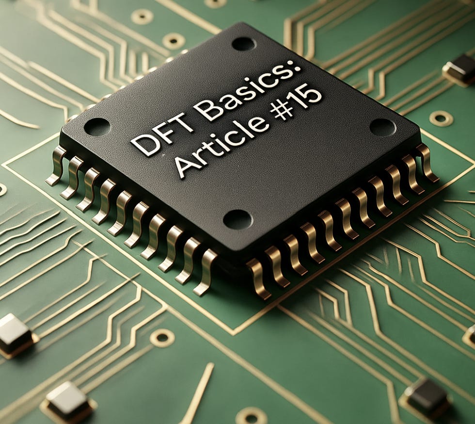
Pipeline flops in Compressor Logic
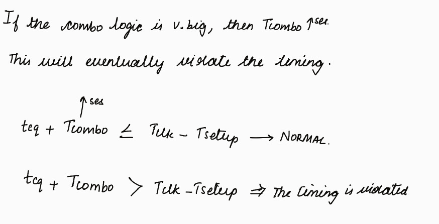
If there are many EX-OR gates present inside the compressor, it is very difficult to meet the timing.
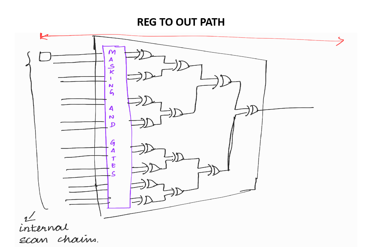
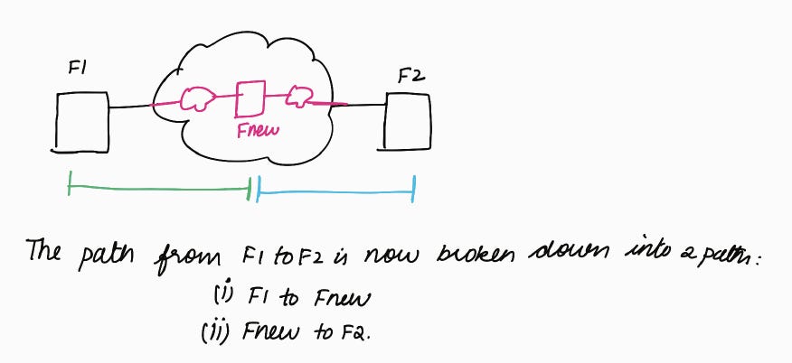
In order to easily meet the timing, pipeline flops are added so that the big reg to out path will be broken into 2 paths – reg to reg and reg to out
We will try to explore the concept of pipeline flops in the compressor using the following example.
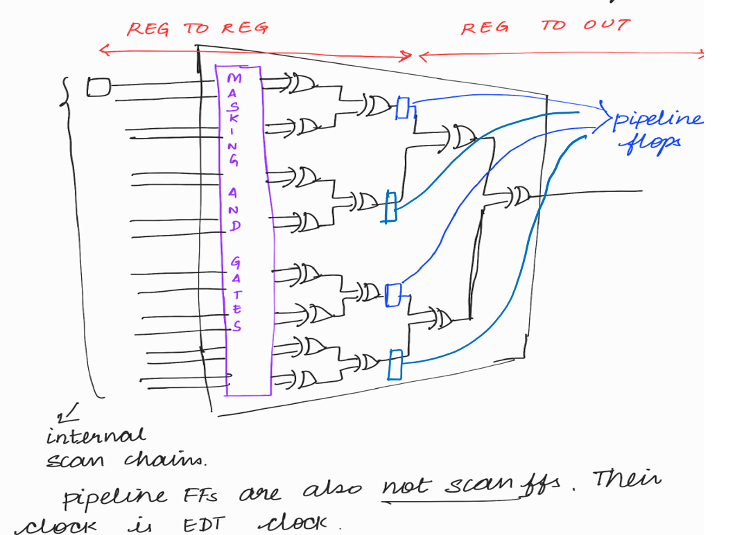
Consider the below reg to reg path,
where, L.F stands for Launch Flop
C.F stands for Capture Flop
tcq stands for clock to q delay Tcombo stands for combinational logic delay
Tclk stands for Time period of clock
Tst (or) Tsetup stands for setup time
< < Setup time is the minimum amount of time before the clock active edge during which the data must be stable> >
Solution :
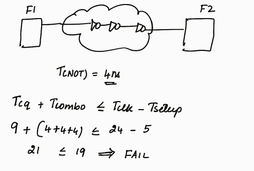
Example :
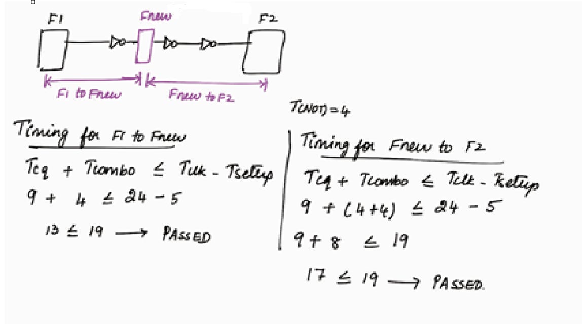
Solution :
The same principle which is discussed in this example is applicable in the case of pipeline flops in the compressor (or) compactor logic.
DEBUG OF EDT PATTERNS
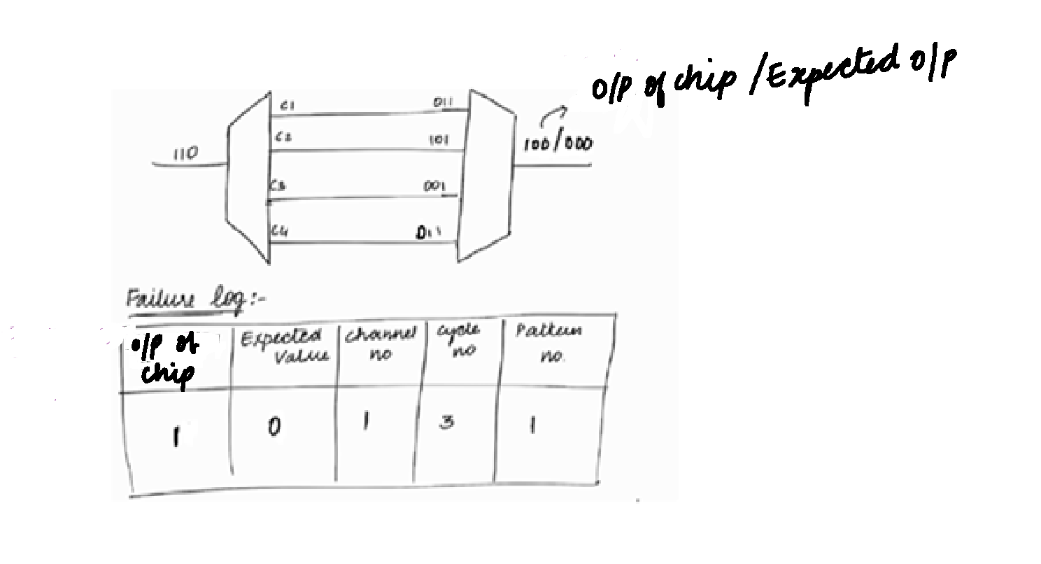
After manufacturing, when the chips are tested on ATE, if output of chip is not equal to the expected value, the chip has failed on the ATE. If a pattern fails on ATE, from the failure log, we will only get the information about in which channel the failure has happened. But a channel will be internally driving multiple chains. In order to find out, in which chain the failure is happening, we generate 1-hot patterns.
We will try to understand this with the help of the below illustration.
Cycle 3 will come for chain 1, chain 2, chain 3 and chain 4.
But we exactly don’t know in which chain mismatch has occurred.
So, we go for 1-hot patterns.
Generating 1-hot patterns
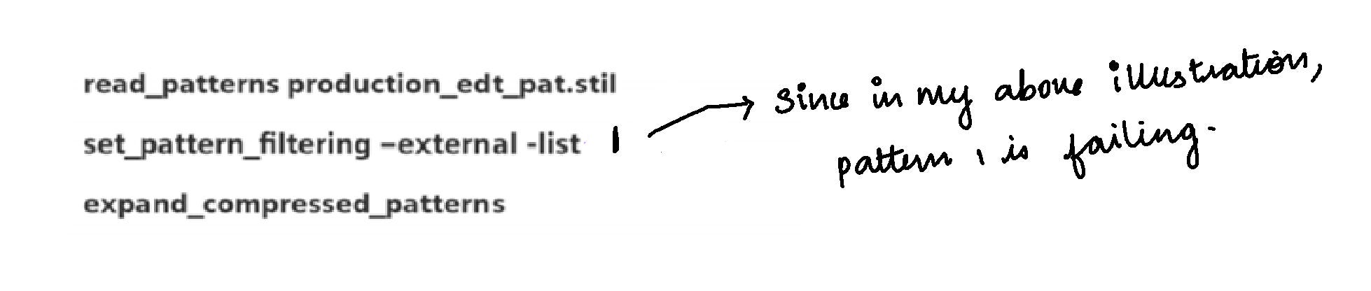
After manufacturing, if patterns fail on ATE, we will know which pattern is failing. If we give information about which pattern is failing to the tool, the tool will generate 1-hot patterns for that particular failing pattern.
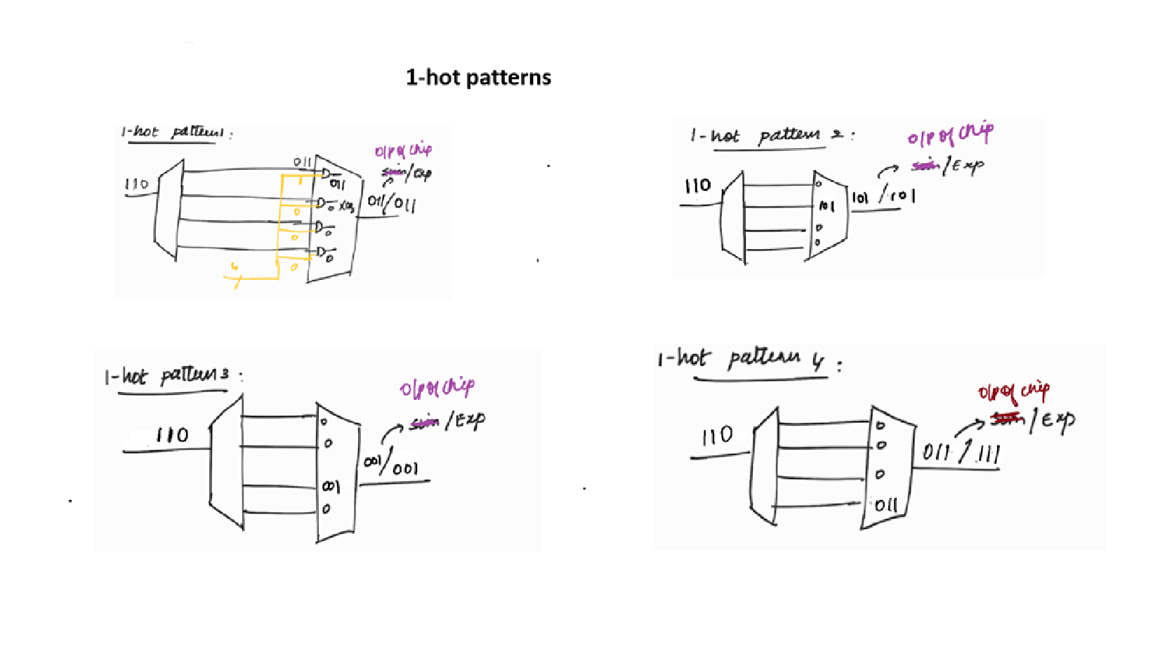
In 1-hot pattern, for each pattern only 1 chain will be enabled in a channel.
In the above picture, the AND gates in the compressor logic are the masking logic AND gates. The inputs to the masking logic AND gates are scan chains outputs and decoder’s output. We have explored this in DFT Basics : Article #13. In 1-hot pattern, for each pattern, only 1 chain will be enabled in a channel. Other scan chains will be masked (by making the input of the AND gate which is coming from decoder as 0)
1-hot patterns will observe only 1 chain at a time in a channel. So we can find in which chain the failure is happening.
In the above illustration, when only chain 1 is observed, test is passed. Similarly when only chain 2, chain 3 are observed, test is passed. But when only chain 4 is allowed, test is failed. So we can find out the the problem is in chain 4.
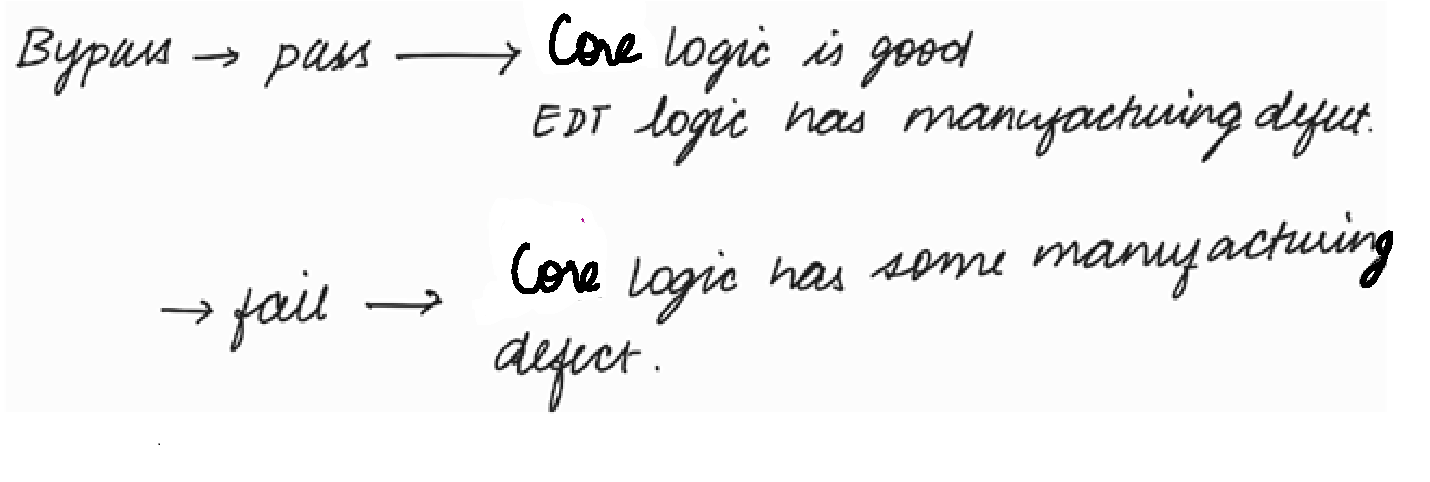
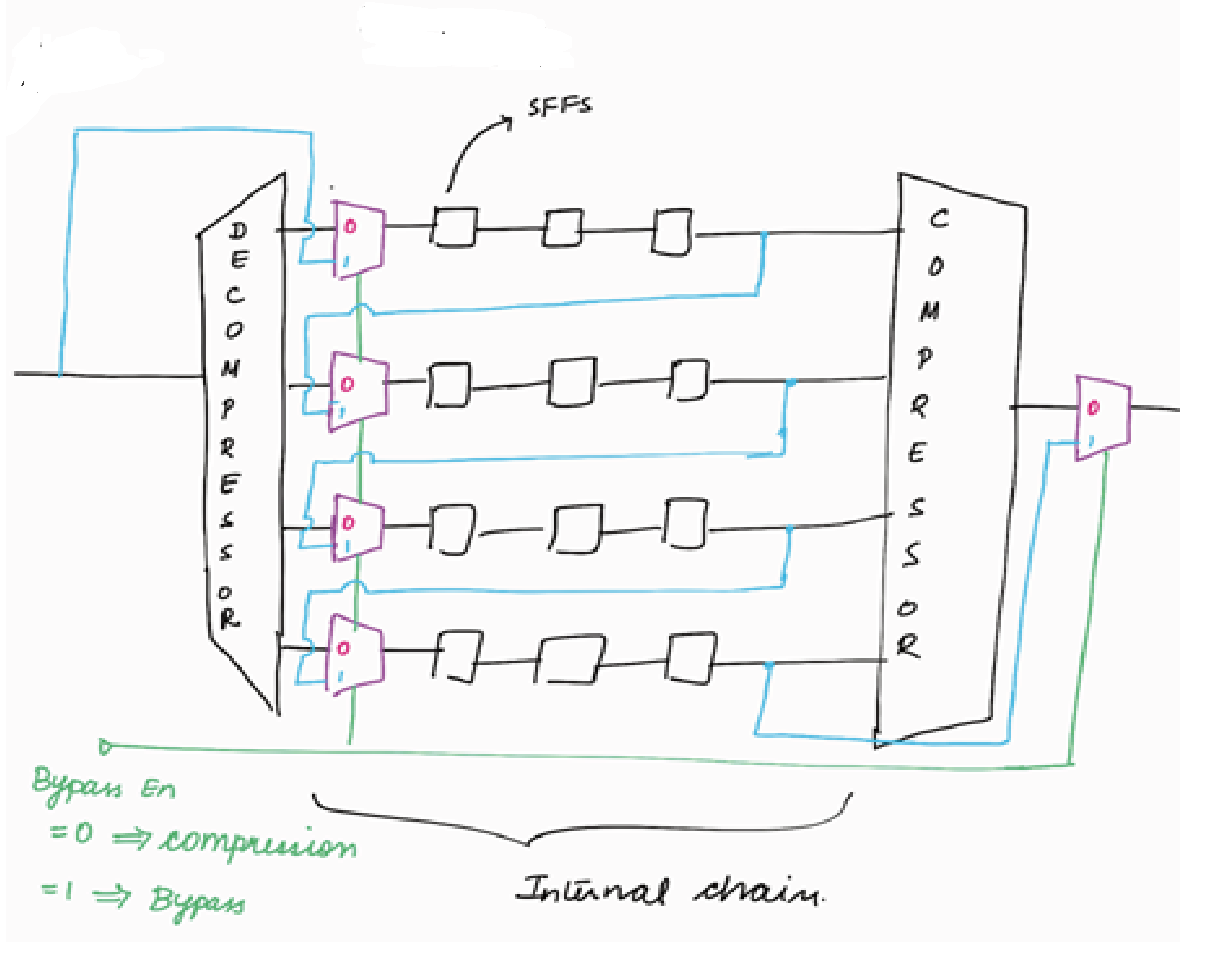
Bypass Logic
The other method to debug pattern failure is to go for bypass (bypassing the EDT logic). Bypass is used to find out whether the manufacturing defect in the EDT logic or in the core logic. If patterns with EDT fails, we can apply bypass patterns. Bypass patterns are the patterns which is generated after bypassing the EDT logic.
When Bypass_en = 1, the EDT logic (Decompressor logic and Compressor logic) is bypassed as shown in the above figure.
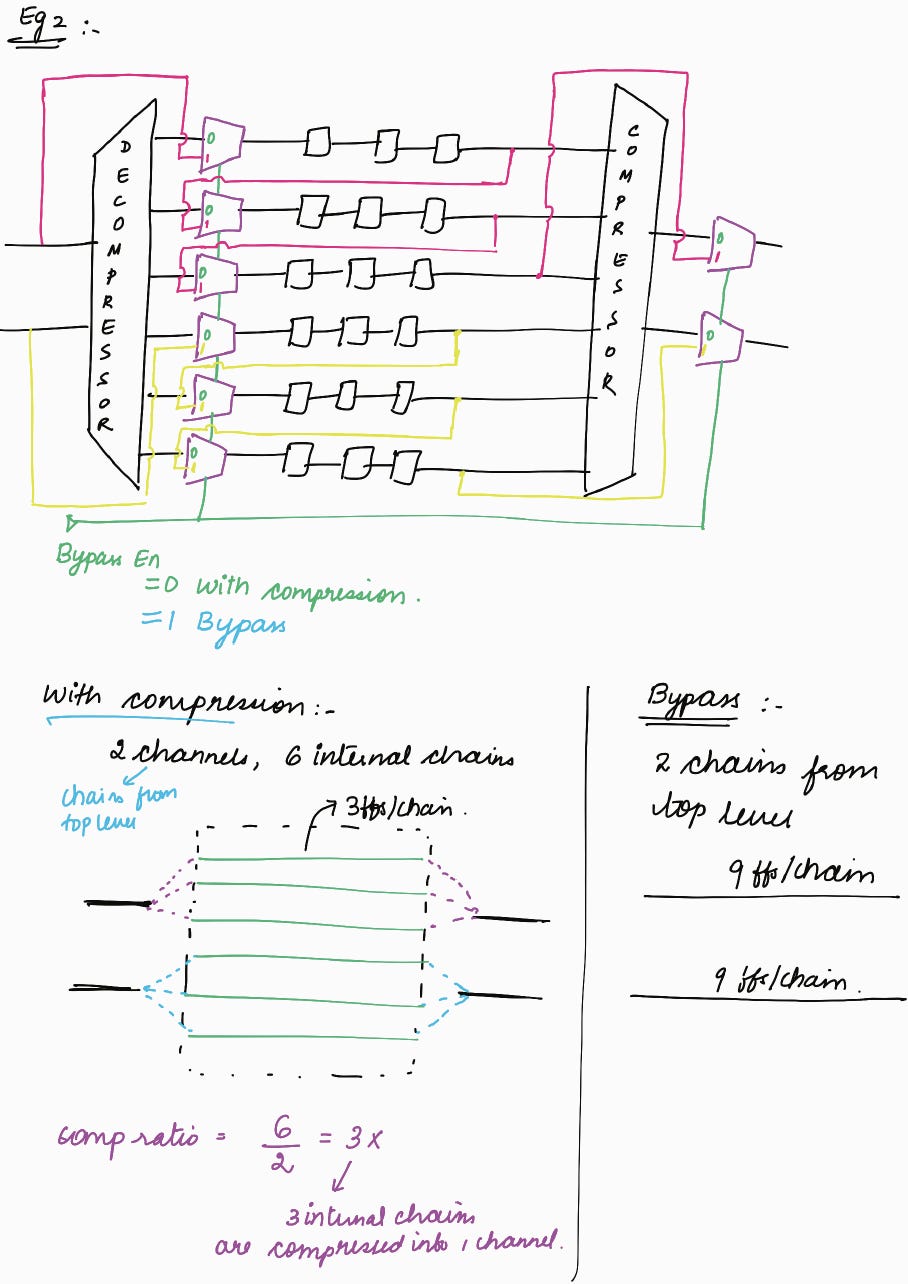
Example 2 :
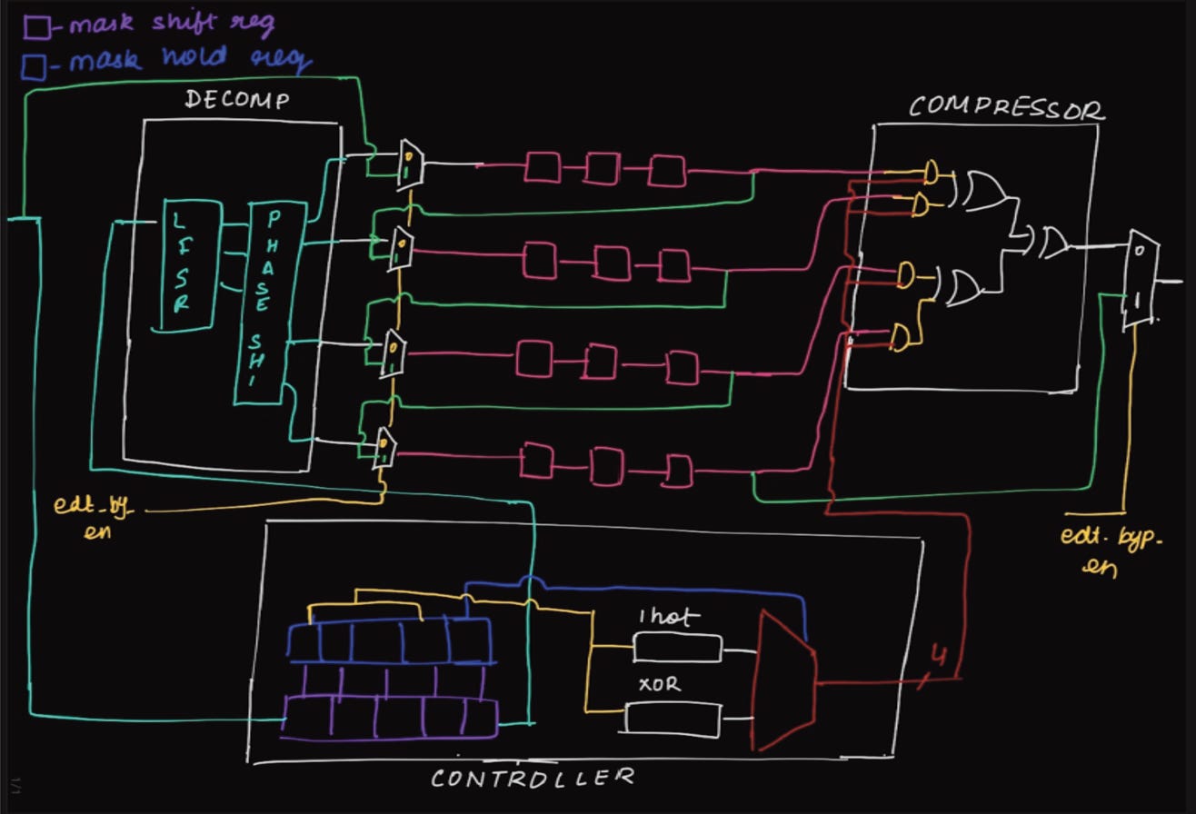
The above 2 examples are drawn without considering the mask shift registers.
When mask shift registers are considered :
In this blog, we had explored pipeline flops, 1-hot decoder and bypass logic in the EDT architecture. In the next blog, we will explore Lock up cells in EDT. We will also explore compression ratio in greater detail, including the merits and demerits of high and low compression ratio.