In my previous blog DFT Basics : Article #7, we explored scan chain balancing — its need, its impact on test time, and the ways to achieve it. In this blog, we will focus on the problems encountered during edge mixing and the methods to handle them.
Edge Mixing :
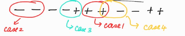
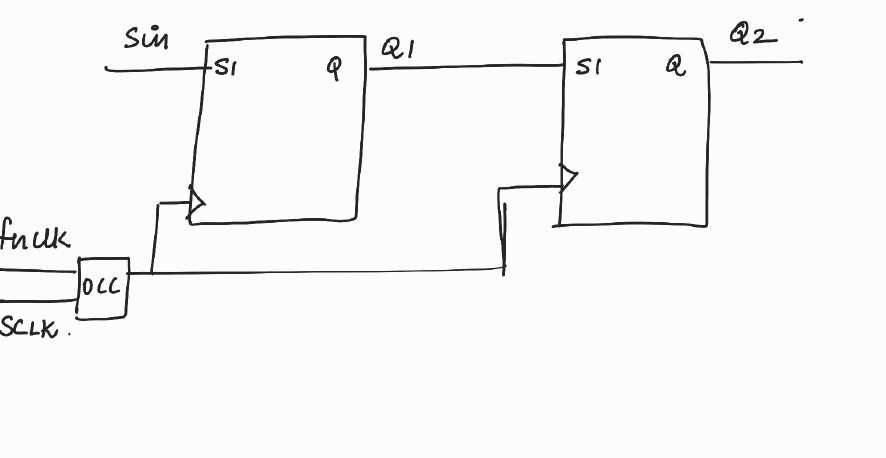
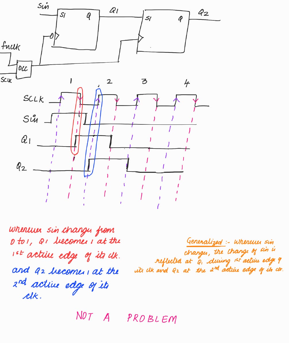
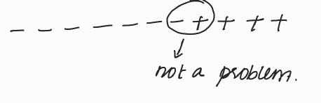
Keeping both positive and negative edge triggered flops in the same scan chain.
< < We will discuss this at the end and explain why it is not a problem. > >
NOTE :
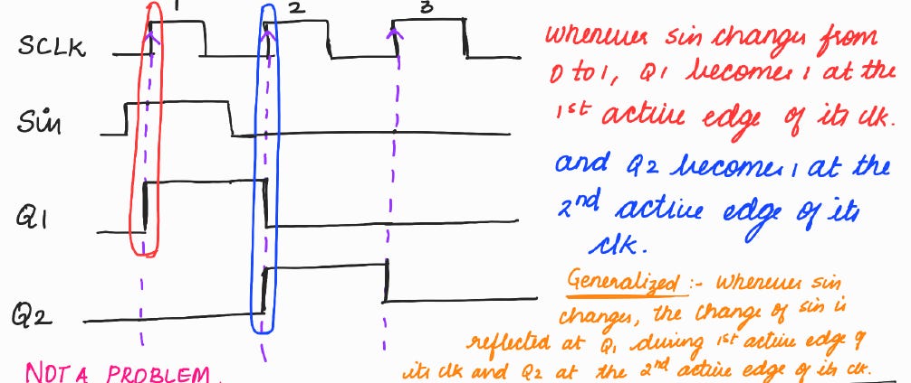
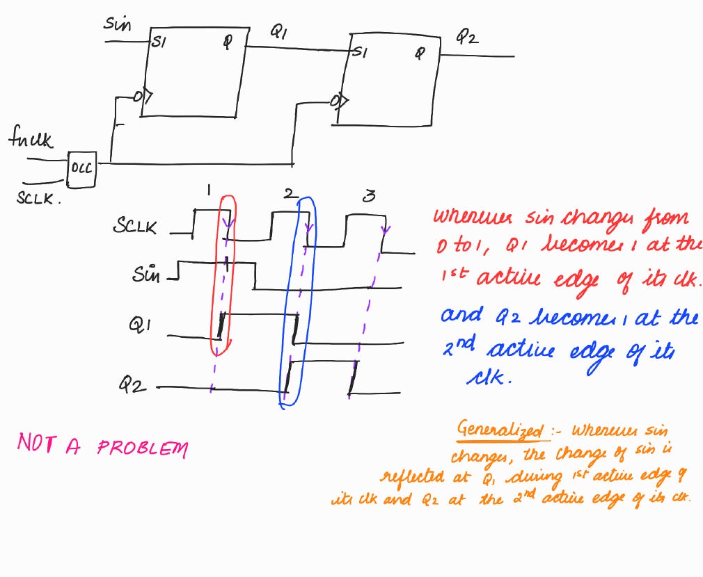
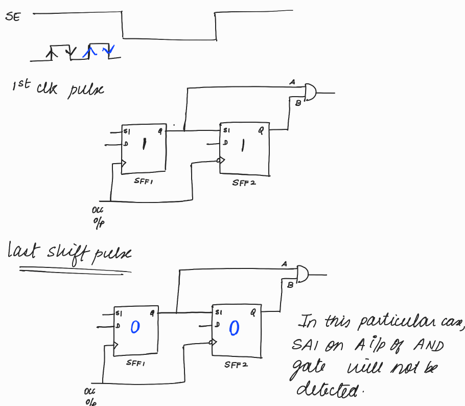
In the above waveform, whenever Q1 is changing at the clock edge, we consider that flop 2 will sample the previous value of Q1. It is because, practically Q1 will not change exactly at the clock edge. There will be a slight clk to q delay. There will also be a net delay while the value of Q1 is propagated to the input of flop 2.
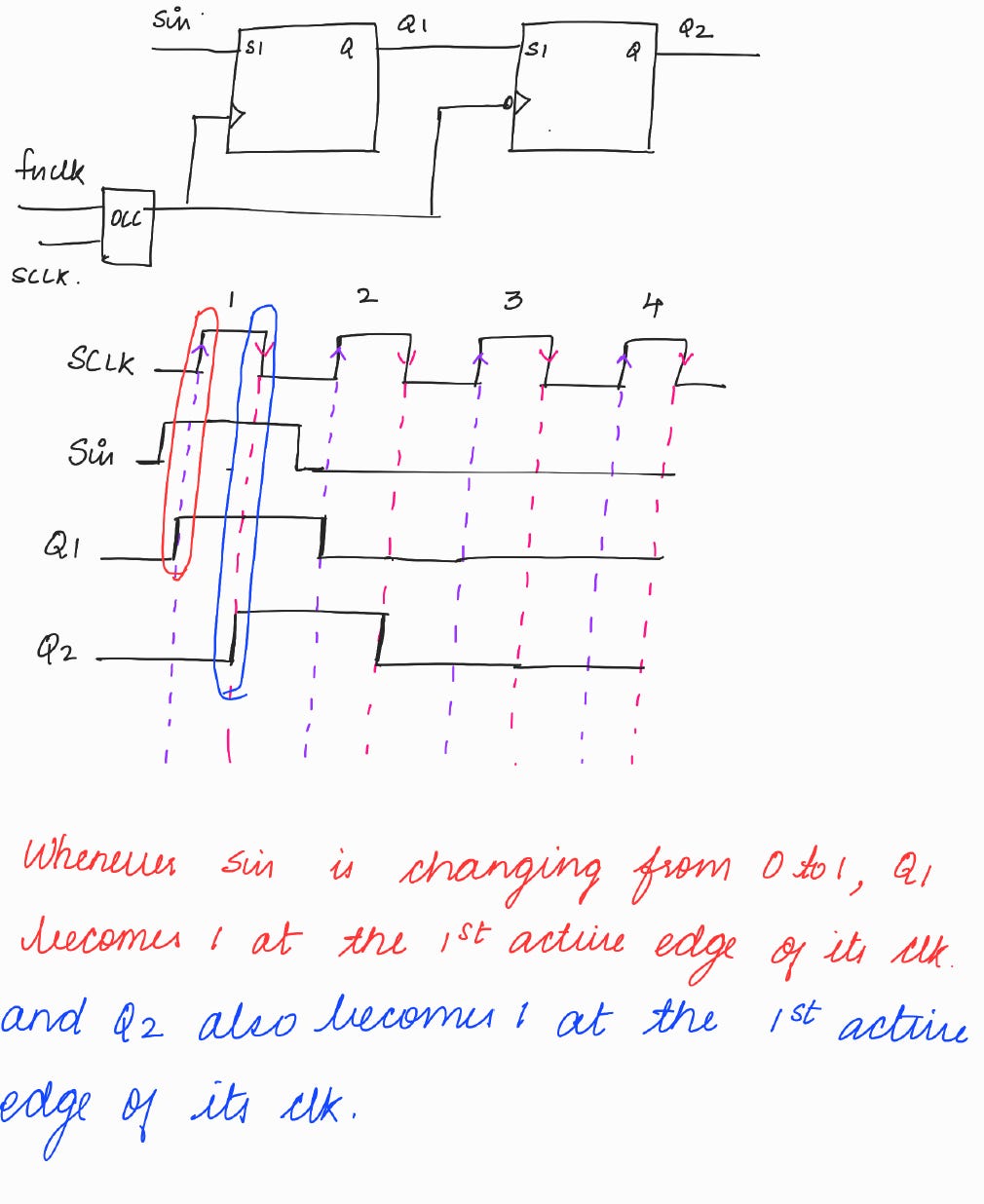
There are two shifts in the same clock pulse. We will not be able to keep two different values in these two flops during a clock pulse. The faults which require different values in these two flops will not get detected.
Illustration of the above problem
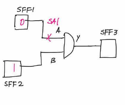
In order to a detect SA1 on the A input of the AND gate, the values of SFF1 and SFF2 should be as shown in the figure below :
In this case, the SA1 on the A input of the AND gate will not be detected, as we are unable to hold ‘1’ value in SFF2 due to this arrangement. < < This is also depicted in the waveform above > >
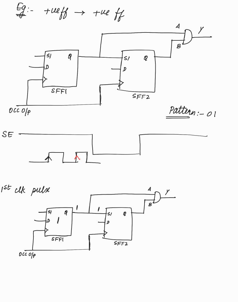
This problem will not occur in the other three cases.
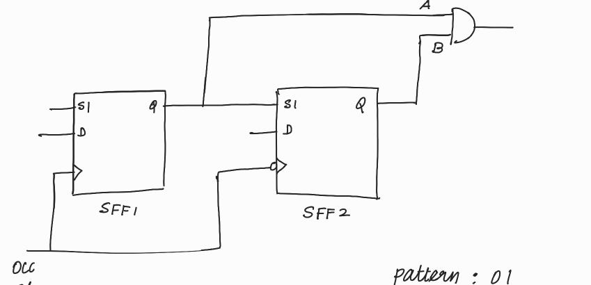
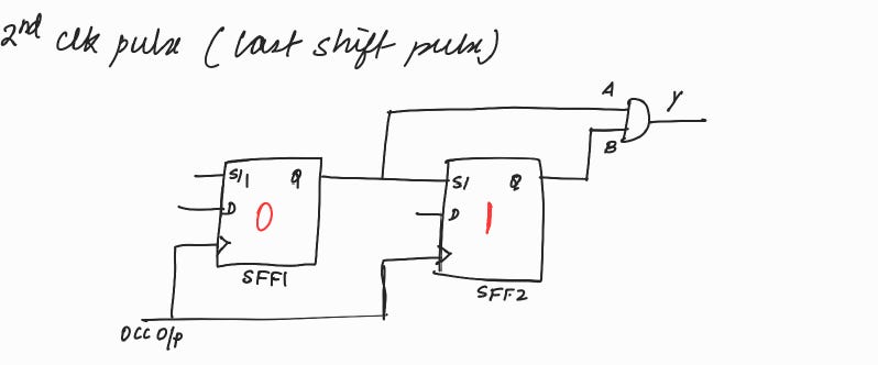
In this case, we are able to keep two different values in these 2 flops during a clock pulse. Therefore we will be able to detect the SA1 fault on the A input of the AND gate.
This applies to the other cases as well.
< < This is also depicted in the waveform above > >
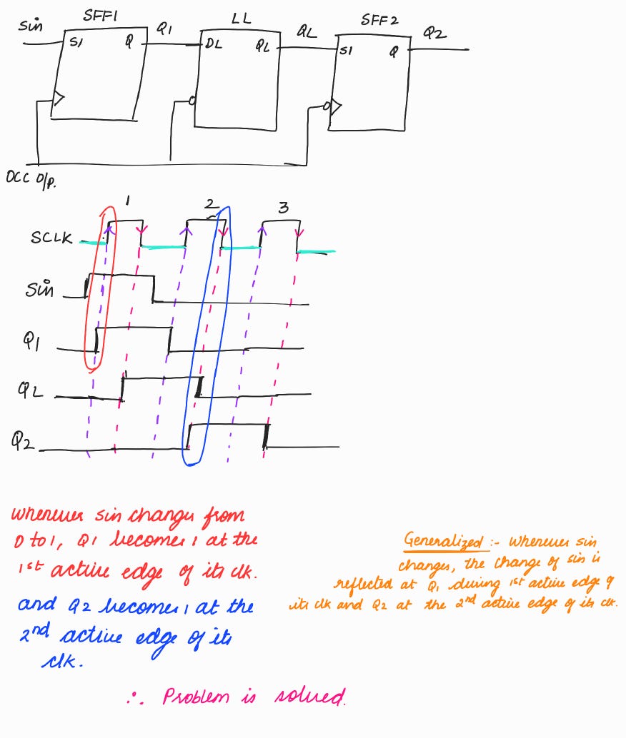
Solution for the above problem :
Insert a lock-up latch.
As seen in the waveform above, the issue of two shifts in the same clock pulse is resolved.
Note :
In Tessent Scan tool, while doing scan chain stitching, the tool tries to place all negative flops in the beginning of the scan chain.
If the tool is unable to do so, and if there is positive ff → negative ff, it will insert a lock-up latch.
In this blog, we had explored the problems encountered during edge mixing and the methods to handle them.
In the next blog, we will focus on the problems encountered during domain mixing and the methods to handle them.