InDFT Basics : Article #21, we have explored Transition Delay Fault Model (TDF). We have also explored the ways of detecting Transition faults (LOC and LOS techniques). We have also explored the Pipelined Scan Enable (PSEN) architecture.
Have you ever wondered why we need Path Delay Fault Model (PDF) when we have Transition Delay Fault Model (TDF)?
Let’s explore !
I recommend reading the following two posts before continuing with this article.
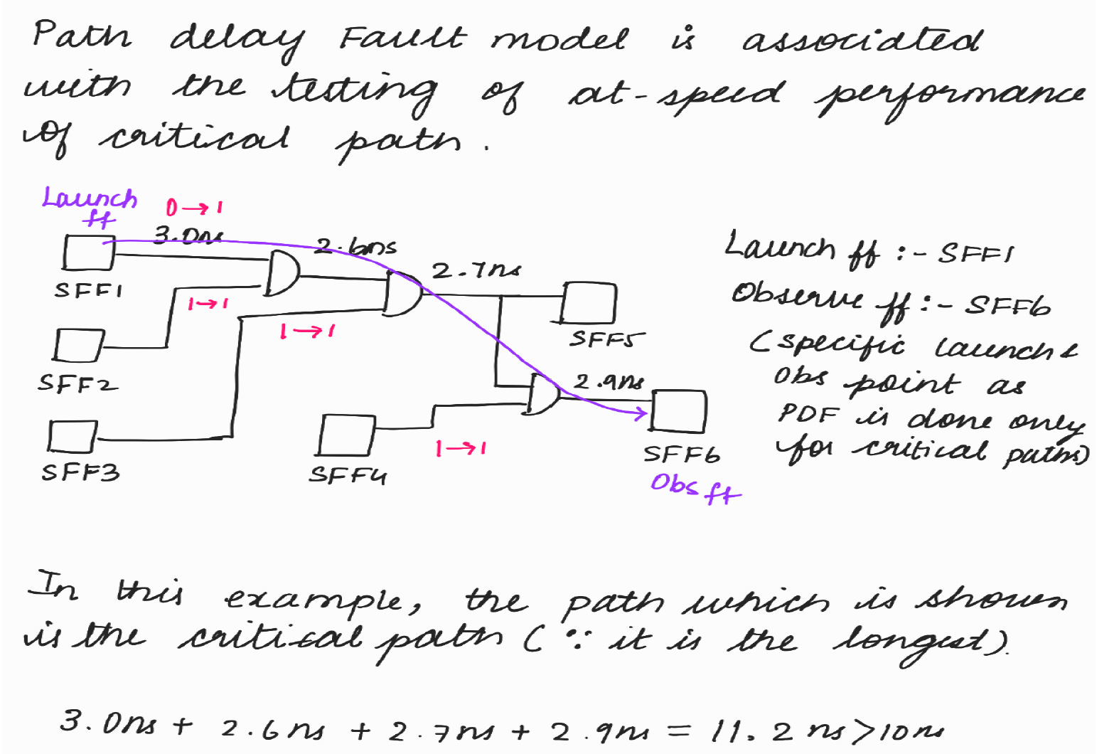
• Associated with testing at-speed performance of critical path (given by
designer).
• Longest path or the path whose clock frequency is high is usually defined as
critical path because timing violations are more likely to happen.
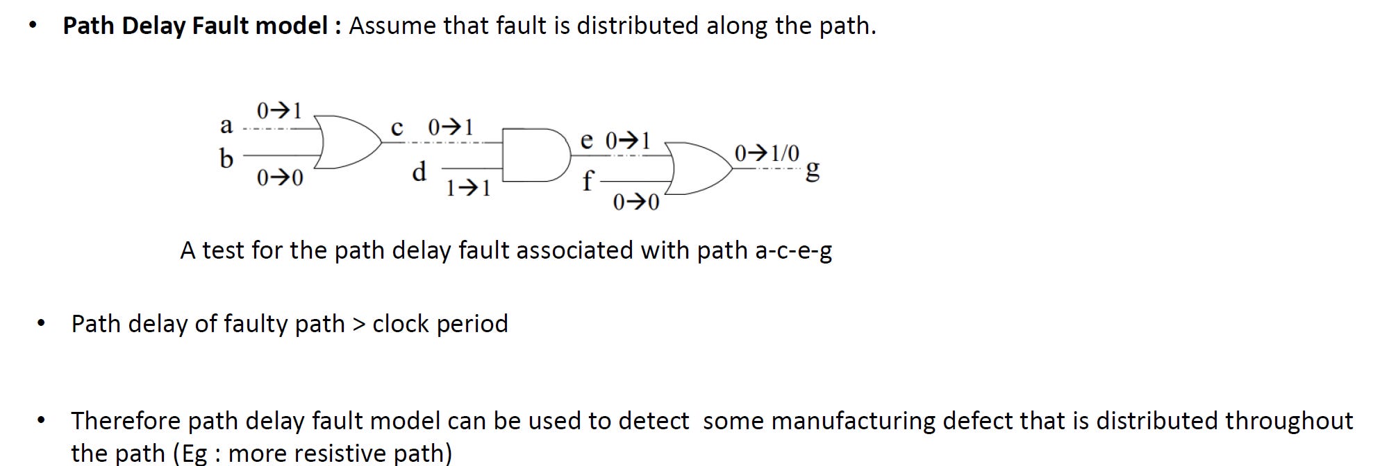
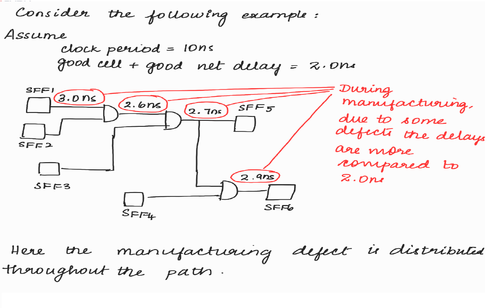
• Path delay fault model : Path delay of faulty path > clock period
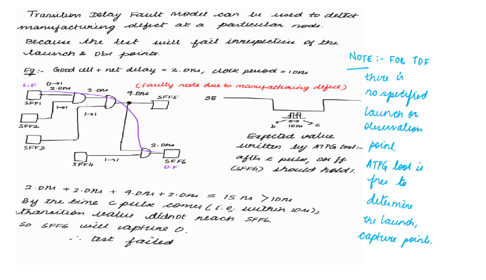
• Path delay fault model is used to detect some manufacturing defect that is
distributed throughout the path (Example : more resistive path)
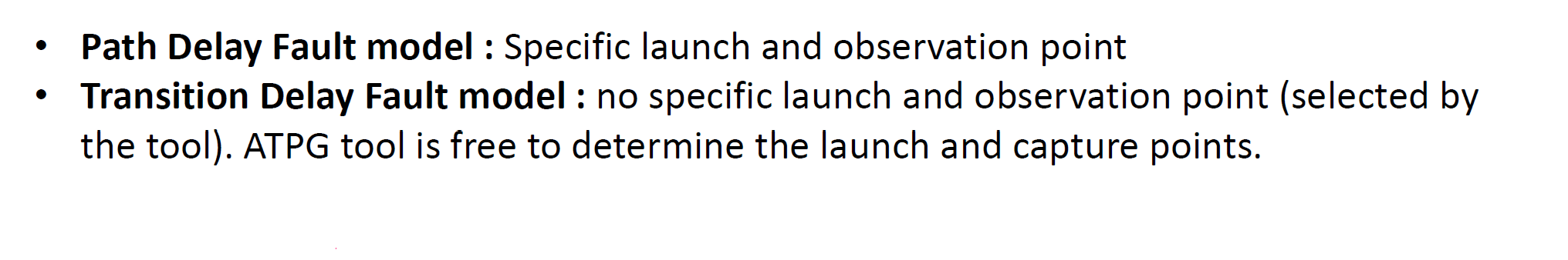
DIFFERENCE BETWEEN PATH DELAY FAULT MODEL (PDF) AND TRANSITION DELAY FAULT MODEL (TDF)
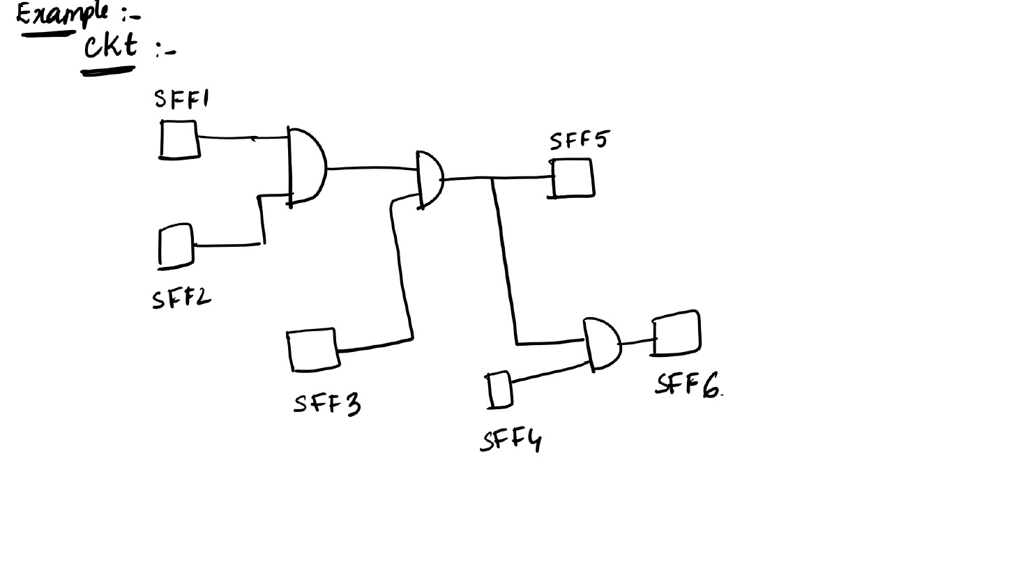
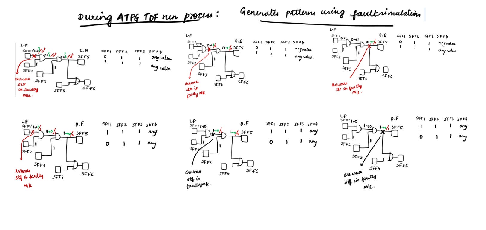
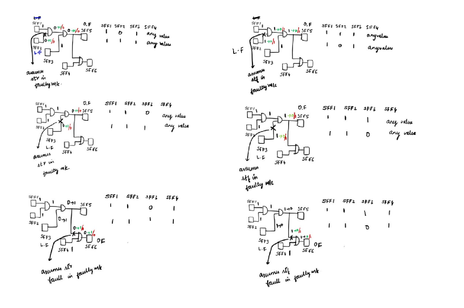
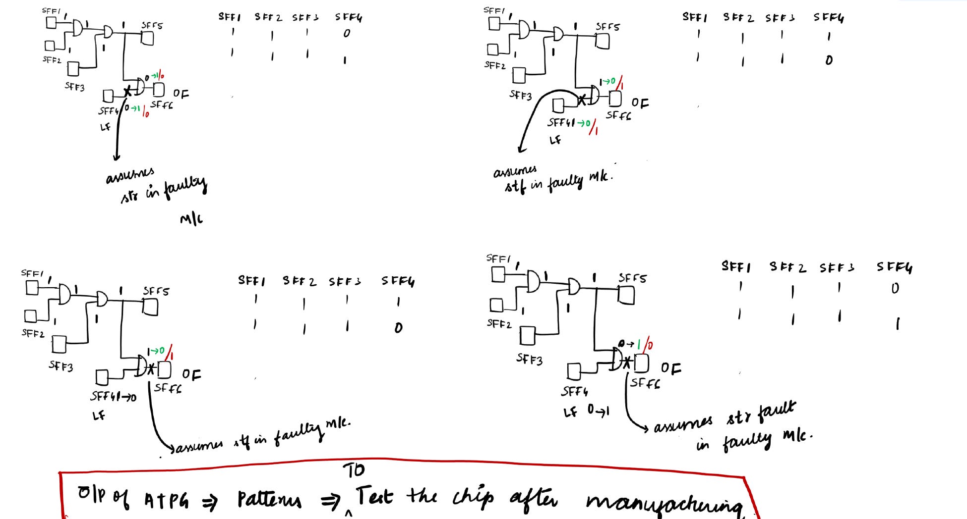
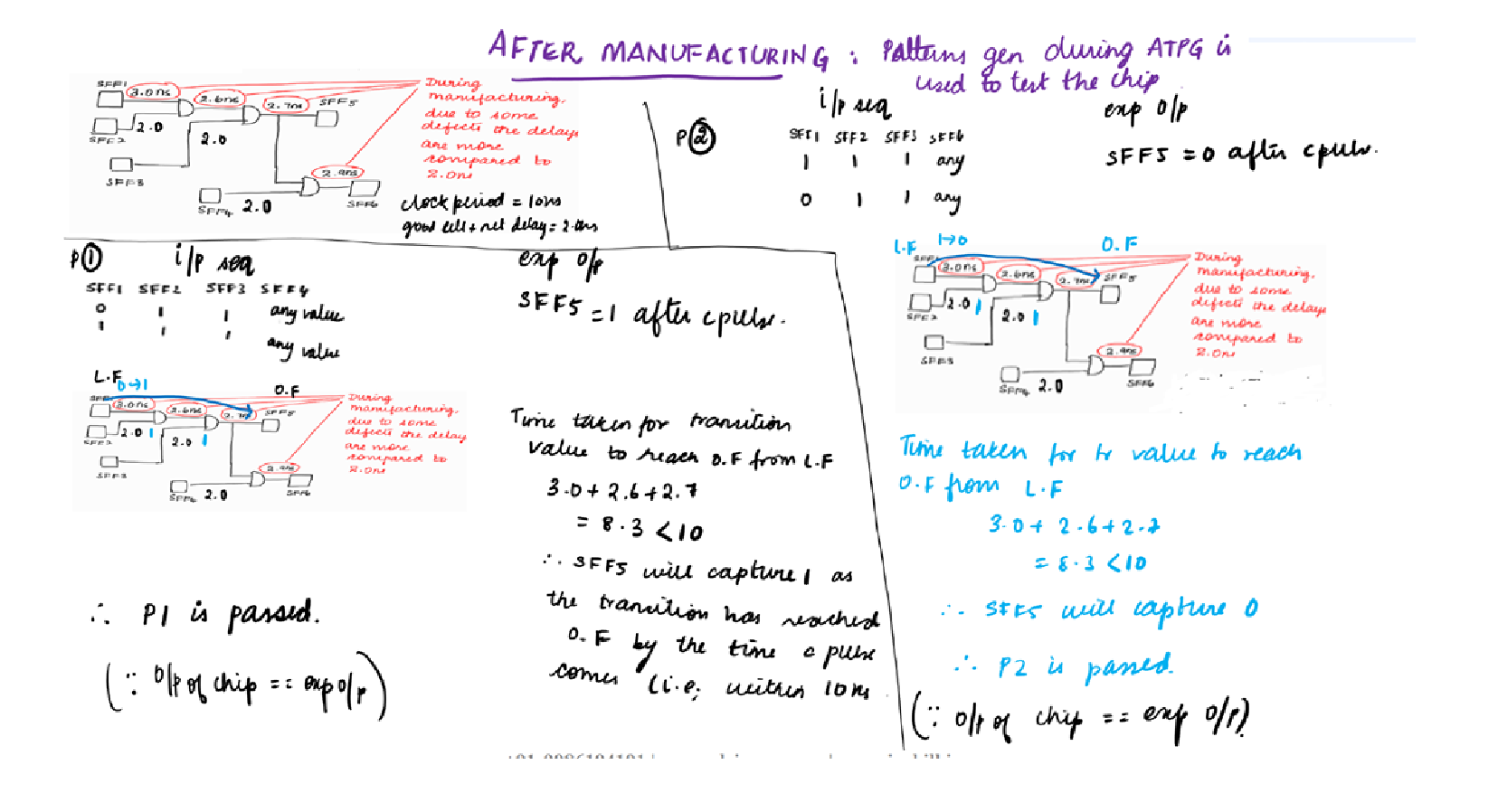
Let’s try to explore the difference between PDF, TDF and the need of PDF when we have TDF through the below illustrations :
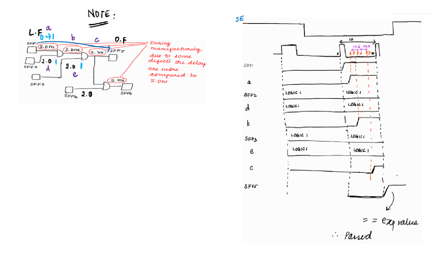
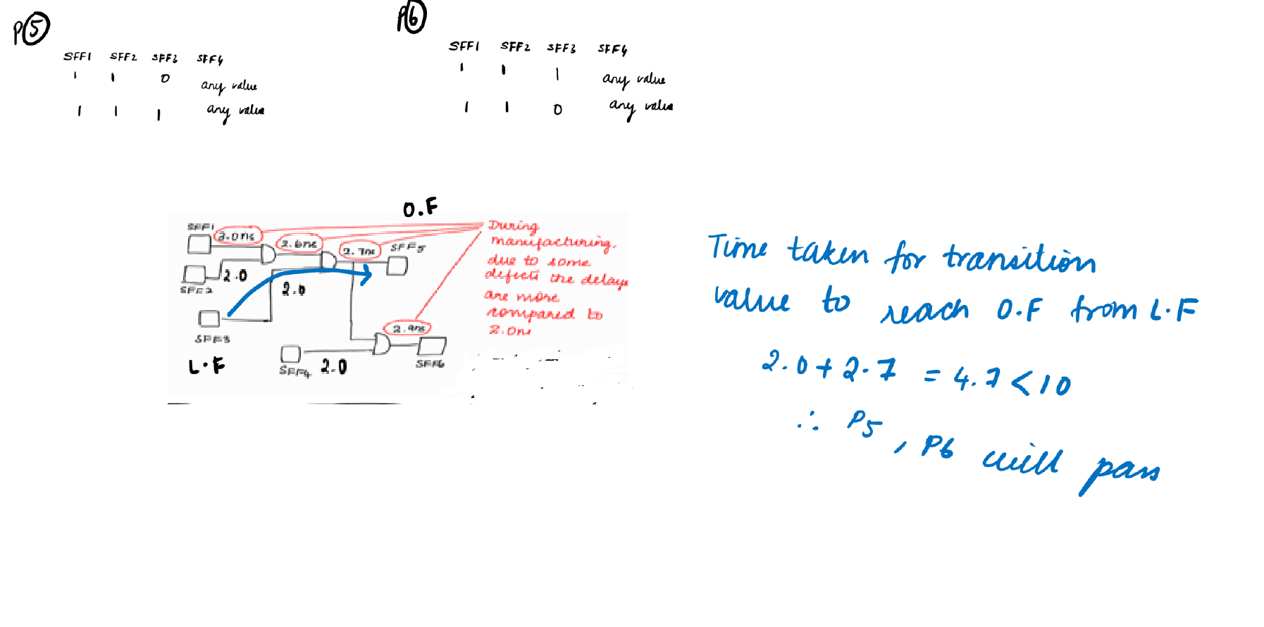
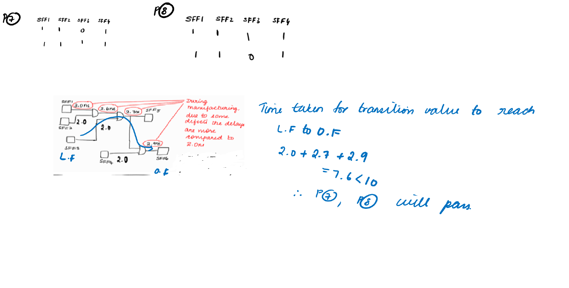
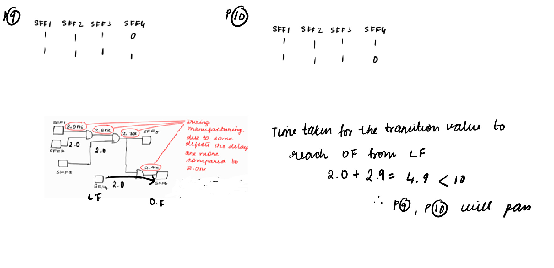
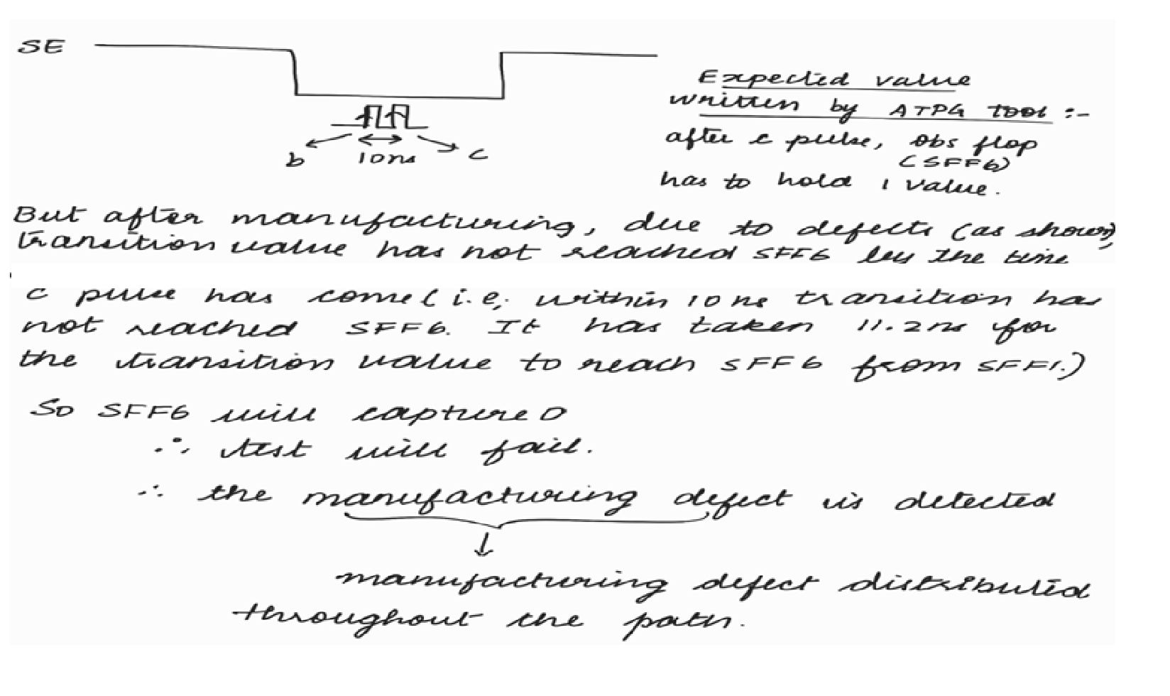
Waveform explanation of the above illustration (1st diagram):
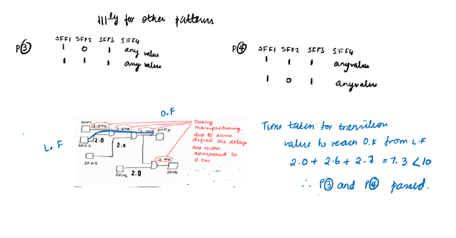
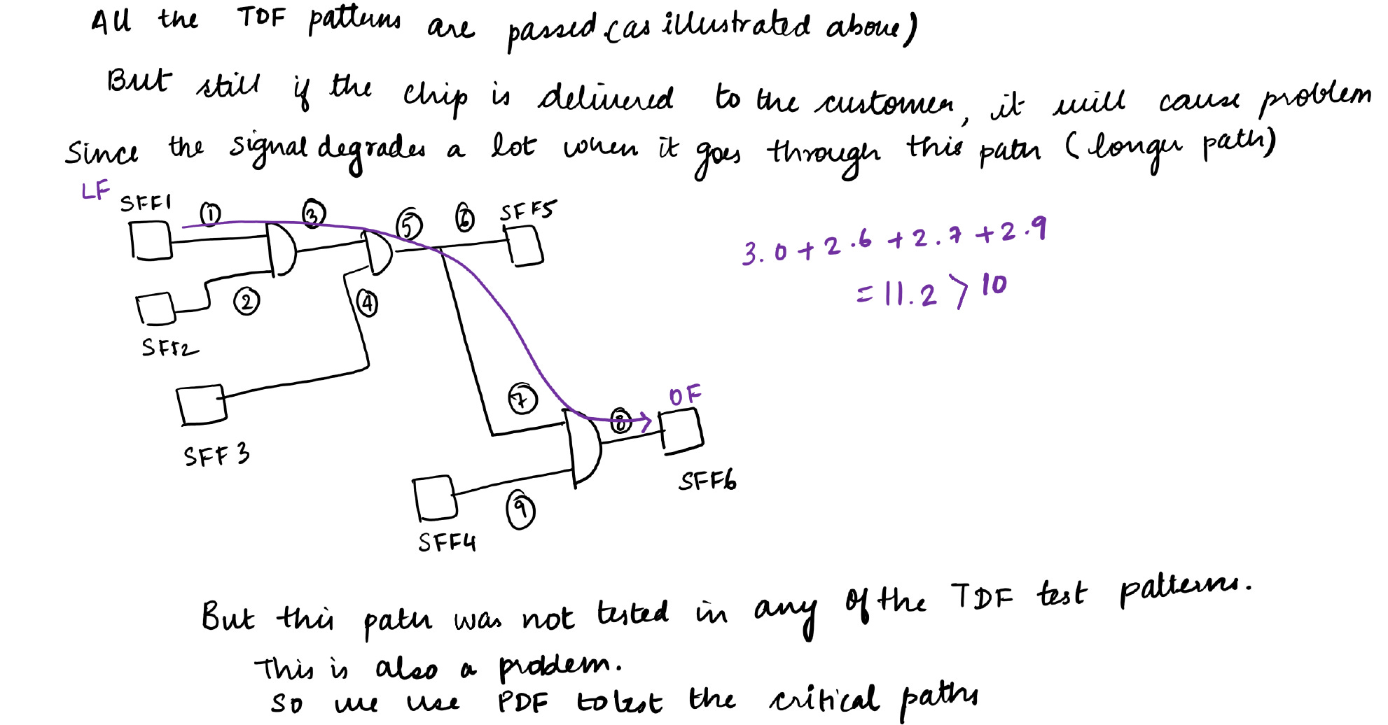
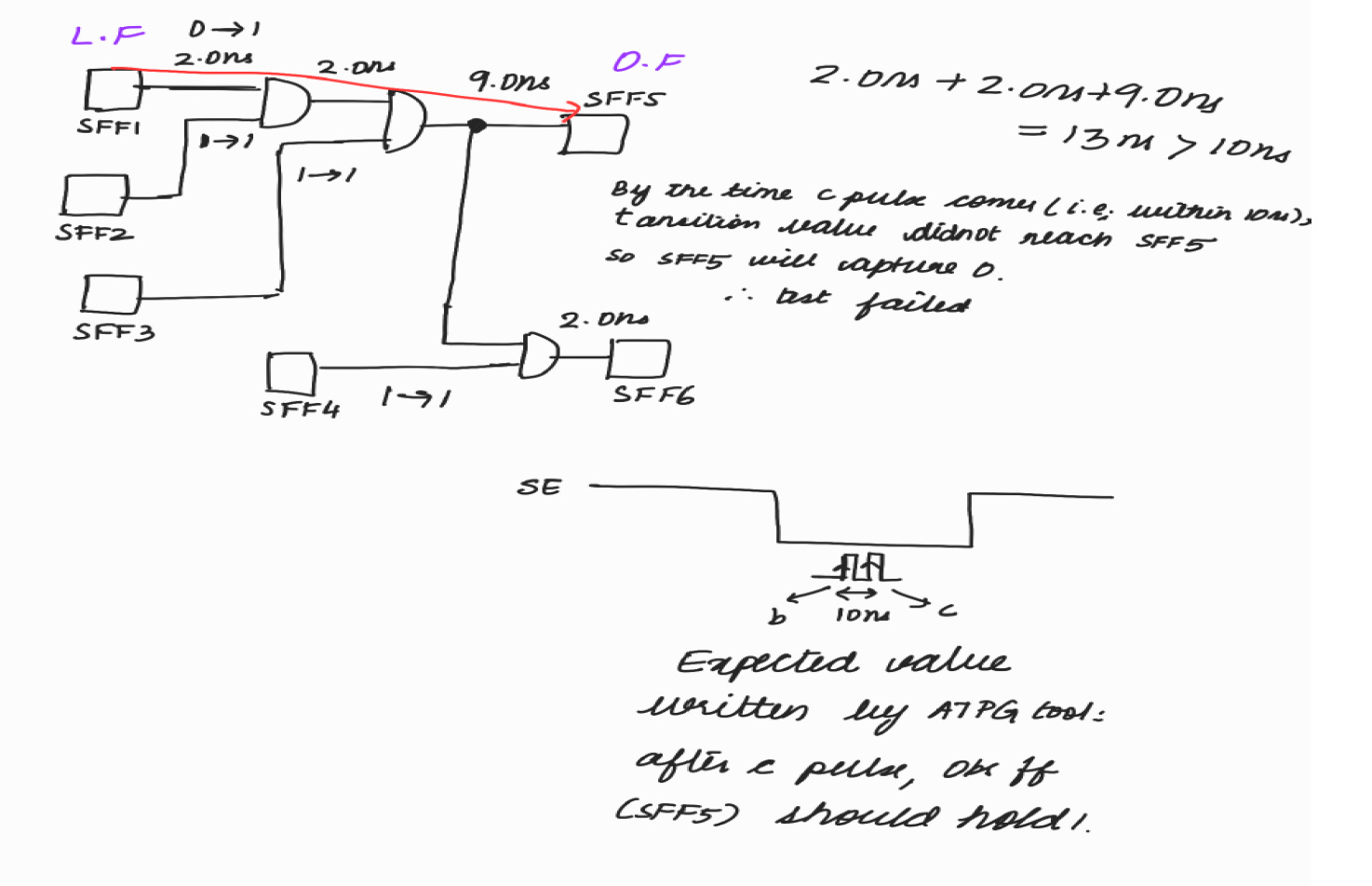
Summarizing the above illustrations :
We need both PDF and TDF because, with only TDF, we can’t assure that manufacturing defect which is distributed throughout the path will get detected. So we usually do PDF to test critical path.
Run-time of PDF is high. So we usually do PDF to test the at-speed performance of critical path. To test the other paths, we use TDF.
References:
Transition Faults and Transition Path Delay Faults: Test Generation, Path Selection, and Built-In Generation of Functional Broadside Tests