
Scan DRC (Part 1)
DFT Basics: Article #5


In my previous blog DFT Basics: Article #4, we explored the concept of clock propagation during scan testing, and the challenges associated with handling clocks in DFT.
In this blog, we will dive into some common Scan DRCs (Design Rule Checks) violations, their impact and how to resolve them.
Design Rule Checks (DRCs)
These are the rules which every flop in the design has to pass in order to be scannable.
List of Scan DRC :
Clock Controllability DRC
Set/Reset Controllability DRC
The above 2 DRCs are important DRCs in scan insertion. If a flop has these 2 DRCs and if we have done the scan insertion without fixing these 2 DRCs, then those flops will not be converted into scan flops.
Feedback Loop DRC
X source DRC
Potential Race DRC
Bus contention DRC
If we have have done scan insertion without fixing these DRCs, then the flops will get scanned but it will cause problem during the later stages.
Clock Controllability DRC:
The clock signal for a flop should be controlled from top level during DFT mode. Else it will lead to clock controllability DRC.
NOTE :
The clocks of all the flops should be coming from OCC output during DFT mode as we had discussed in my previous blog DFT Basics: Article 4.

Scenario which will cause clock controllability DRC:
If the clock of a flop is controlled by another flop or any combo logic’s output.

This is designer’s requirement.
For example, asynchronous counter design. The design will function like an asynchronous counter only if the FF1’s Q goes as FF2’s Clk.
DFT team’s requirement :
Shift Phase : Slow frequency Clock
Capture Phase : Stuck At fault model - Slow frequency clock, 1 clock pulse
Transition Delay Fault Model - Fast frequency clock, 2 clock pulses.
During DFT mode, the clock of the flop should be coming from OCC output so that the required clock and required no. of clock pulses can be propagated during DFT mode.
We have to fix the DRC in such a way that, the functionality is not affected and the required clock and required no. of clock pulses is propagated during DFT mode.

where TM is Test Mode.
Set/Reset Controllability DRC:
Set/Reset of all flops should be controlled from top level during DFT mode. Else it will lead to Set/Reset controllability DRC.
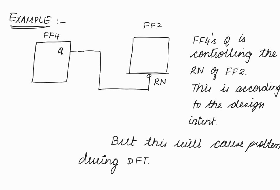
Problem : Proper patterns will not be shifted into the scan chains.
DEMONSTRATION OF THE ABOVE PROBLEM :

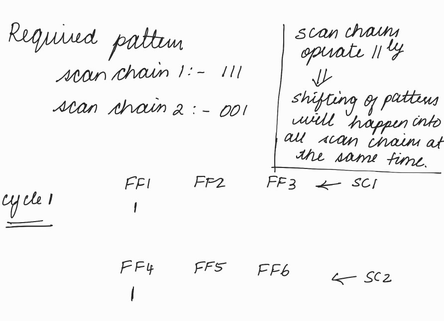

Required pattern is not getting shifted into the scan chains.
Therefore reset of all flops should be controlled from top level during DFT so that our tool has control on when the reset has to be active and when it has to be inactive.
Scenario of getting set/reset controllability DRC:
If the set/reset of the flop is being controlled by another flop or any combo logic’s output.

We have fixed the DRC in such a way that we have not affected the functionality (designer’s requirement) and at the same time, reset is also being controlled from top level during DFT mode.