
Embedded Deterministic Test (EDT) - Lock up cells in EDT and Compression Ratio
DFT Basics : Article #16


In my previous blog DFT Basics : Article #15, we had explored pipeline flops, 1-hot decoder and bypass logic within the EDT architecture.
In this blog, we will focus on lock up cells in EDT and compression ratio.
Let’s get started !
Lock Up Cells in EDT
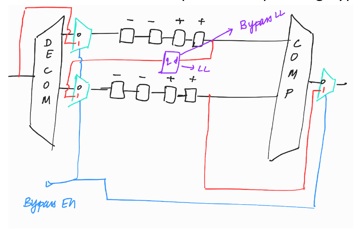
Bypass Lock up
It is added whenever there is +ve flop → -ve flop during bypass.
< <In DFT Basics : Article #8, we discussed the issue that arises when +ve flop → -ve flop. We have also explored how this problem can be resolved by introducing a lock-up cell. > >
Lockups Between Decompressor and Scan Chain inputs
The decompressor is located between the scan channel input pins and the scan chain inputs. It contains sequential circuitry clocked by the EDT clock.
Scan chain clocking does not utilize the EDT clock. Therefore, there is a possibility of clock skew between the decompressor and the scan chain inputs.
< < In DFT Basics : Article #9, we have explored this problem and how it will get resolved by introducing a lock-up cell > >
Lockups at the end of scan chain (terminal lockup)
This is added because of domain mixing. The scan flop’s clock is scan clk and pipeline flop’s clock (inside compressor) is edt_clk.
< < In DFT Basics : Article #9, we have explored this problem and how it will get resolved by introducing a lock-up cell> >
Compression ratio
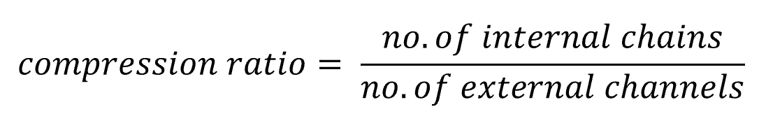
Example :
No. of external channels = 2
No. of internal chains = 100
Compression ratio = 100/2 = 50x
x stands for how many times chains are compressed into channels.
< < Usually compression ratio will be around 80x > >
What happens if compression ratio is exceeded above 100x?
If compression ratio is exceed above 100x, then the probability of getting fault aliasing will be more.
< < We will explore this point in detail in the ATPG section > >
If the compression ratio exceeds 100x, the XOR tree inside the compactor becomes significantly large. This leads to increased area and can cause timing violations, leading to the insertion of pipeline flops.
< < We have explored pipeline flops in DFT Basics : Article #15
Merits and Demerits of high and low compression ratio
no. of external channel 25
10,00,000 flops in the design
Compression ratio = 50x
no. of internal chains 1250
800 flops per scan chain ==> almost equal to 800 shift cycles per pattern
< < Since, no. of shift cycles per pattern = no. of flops in the scan chain + masking bits + initialization cycles > >
no. of external channels = 25
10,00,000 flops in the design
Compression ratio = 80x
no. of internal chains = 2000
500 flops per scan chain ==> almost equal to 500 shift cycles per pattern
< < Since, no. of shift cycles per pattern = no. of flops in the scan chain + masking bits + initialization cycles > >
As seen above, opting for a higher compression ratio increases the number of internal scan chains, which reduces the number of shift cycles per pattern. As a result, both test time and test data volume are reduced.
However, if the compression ratio exceeds 100x, we may encounter the issues discussed above.